prox.pad Plus IR Access System Installer Guide
Communication Board Overview
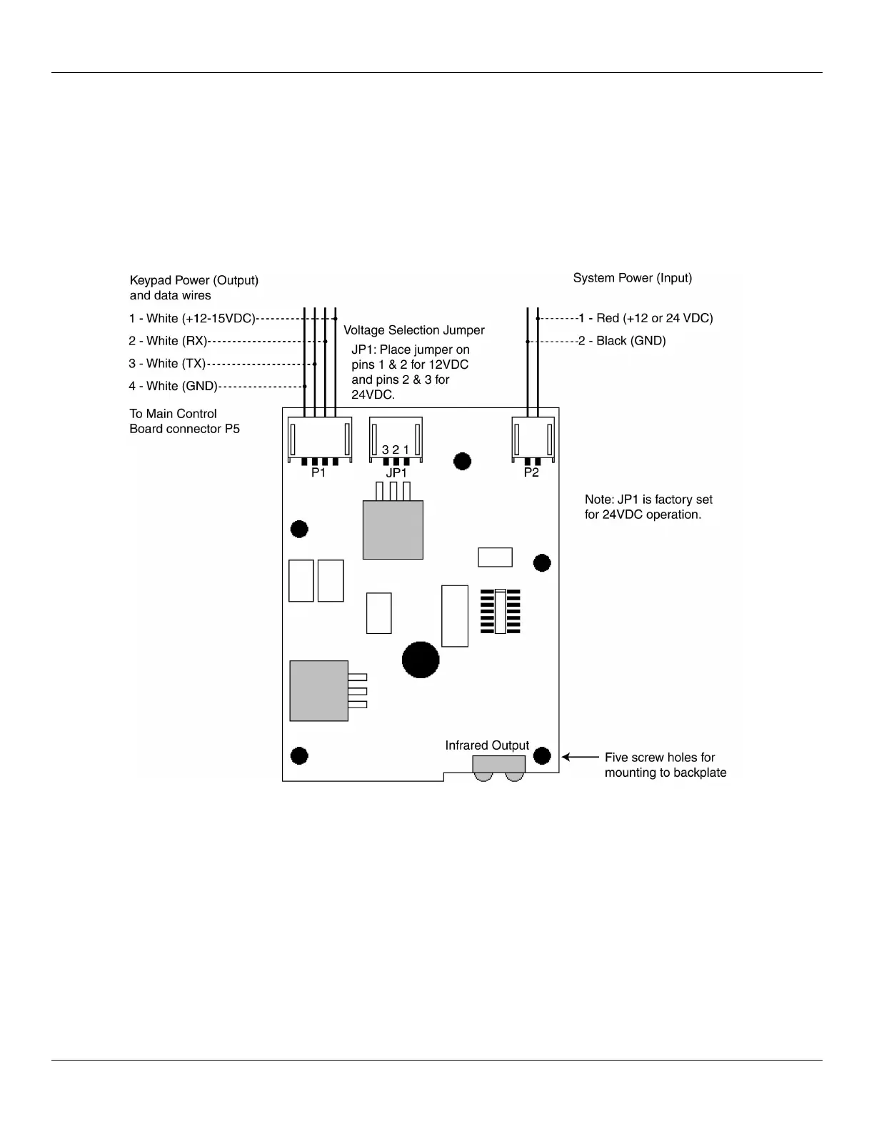
The following diagram shows the various connectors and wire connections on the communication board. The communication board is
packaged separately from the control unit to allow you access to the backplate mounting holes and wire knockouts. You must secure
communication board to the backplate using the five supplied mounting screws.
Please note the system power is connected to P2 in the upper right. You must also set the voltage selection jumper (JP1) to the correct
setting. This is discussed in more detail in a later section.
Document # 6105681, Rev 1.1, D2a Page 11 of 32
Figure 3: Identifying Pin Connectors (Communication Board)