prox.pad Plus IR Access System Installer Guide
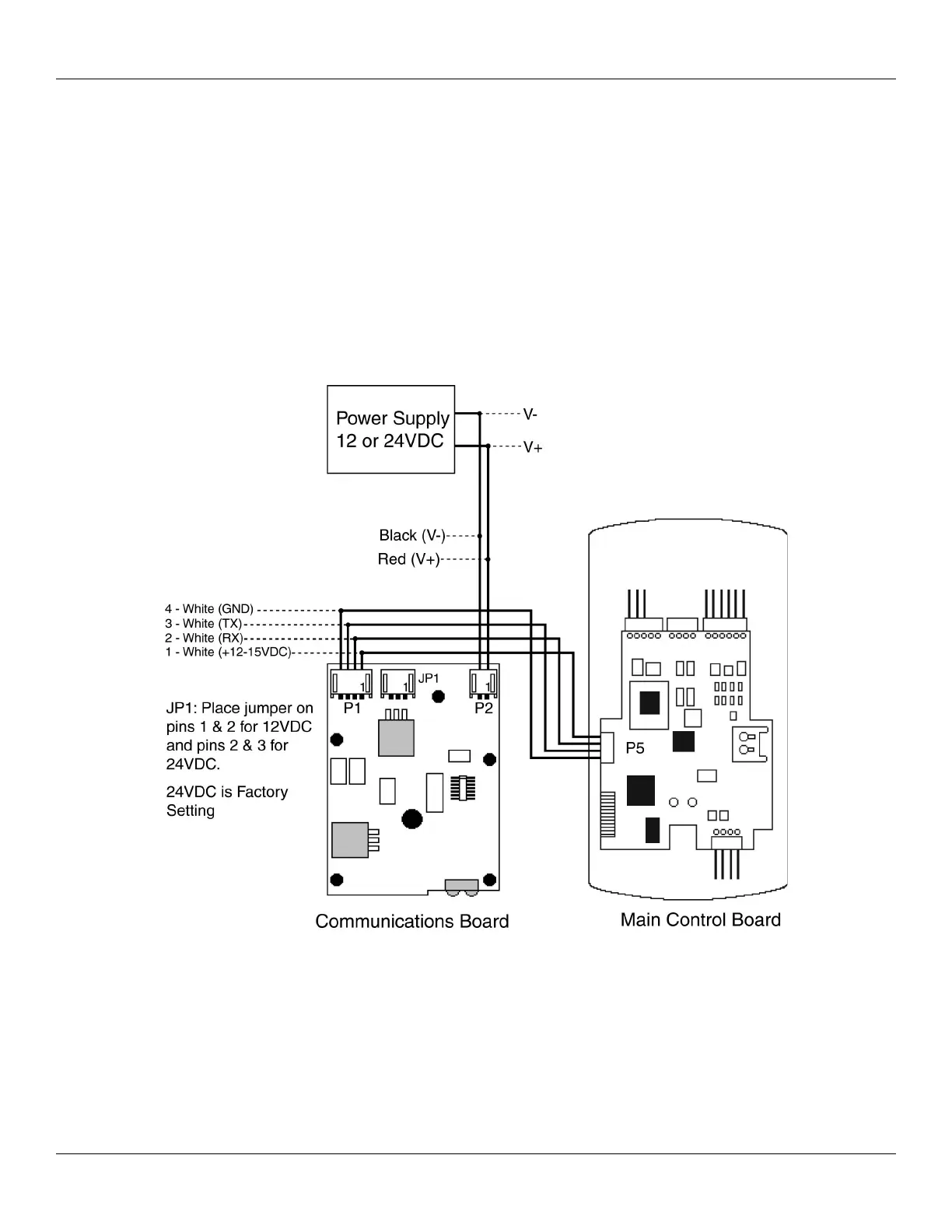
Connecting the Communication Board to the Main Control Board
The prox.pad Plus IR is composed of two circuit boards, the control board and the communication board, which is mounted in the rear
keypad housing. The communication board contains the infrared communications circuitry used for communicating to a PDA device,
as well as the power supply. The power supply circuit should be powered with 12 or 24 VDC. This is selectable by jumper JP1;
24 VDC is the factory setting.
The prox.pad Plus IR unit is powered through P2 on the communication board. Connector P1 on the communication board then
provides power to the keypad control board using the supplied wire harness; this connects to P5 on the control board. The two data
wires for infrared communications are also on this same wire harness.
Document # 6105681, Rev 1.1, D2a Page 19 of 32
Figure 10: Connecting the Communication Board to the Main Control Board