2 - TECHNICAL INFORMATION VIP80E-II
EN
2 - Pag. 17 / 28
2.3 SAFETY DEVICES
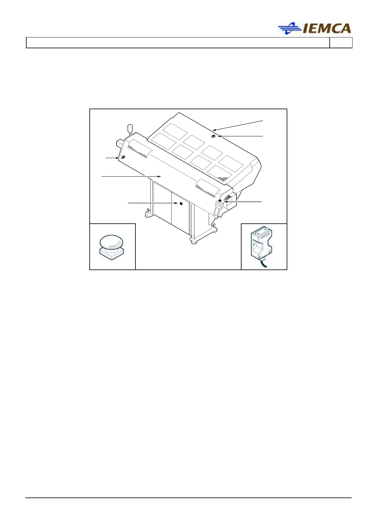
The figure indicates the position of the devices on the bar feeder.
B
B
A1
A
8070_02_06_1
B
C1
C
A1
C1
A- Sliding guard: it is associated to a microswitch (A1). At the opening of the guard, in
emergency conditions, all the bar feeder and lathe functions stop. At the guard closing, it is
possible to start the operating cycle again. It is equipped with two grids allowing the visual
inspection of the main components of the bar displacement system.
B- Emergency stop button: if activated, every component of the bar feeder and of the lathe
immediately stops. After having normalised the operating conditions it is required to release
the button, with a voluntary action, in order to authorise the bar feeder and lathe setting
into operation again.
C- Sliding guard: it is associated to a microswitch (C1). Only during the bar change phase, if
the guard is opened, all the bar feeder and lathe functions are stopped in emergency
conditions; during all the other work phases of the bar feeder, it is possible to open the
guards without causing any stopping.
At the guard closing, it is possible to start the operating cycle again. The guard has a grid so
as to allow visual inspection of the bar magazine.



 To Next Page