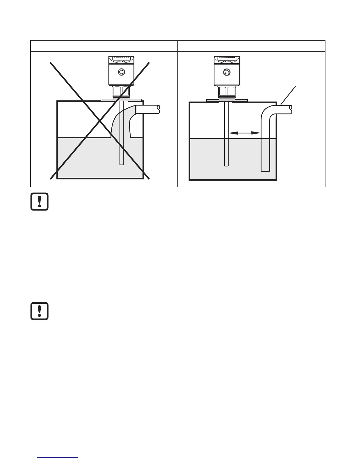
16
the fill pipe and the rod = 50 mm; higher for probe lengths > 70 cm and in case
of heavy soiling (→ 6.1.1).
Fig. 6-3 Fig. 6-4
50mm
A
To avoid incorrect measurements in case of heavy foam formation and
turbulence:
► if possible, install the sensor in a steady area�
Example how to create a steady area:
- Use of a coaxial probe (only for clean, low-viscosity media)
- Installation in bypass or still pipe (see fig� 6-5)
- Separation of the installation location by metal sheets / perforated sheets
(without figure)
Min� diameter of the bypass and still pipe: d = 100�
The upper access to the steady area (fig� 6-5: A / B) has to be above
the maximum level� The lower access (fig� 6-5: C / D) or the area with
perforated sheet etc� has to be below the minimum level� This ensures that
neither foam nor turbulence impact the sensor zone� Besides, the use of
perforated sheets or the like can help to avoid soiling (e�g� by metal swarf,
particles, ���)�