The device may be actuated solely after conrmation of the re protection efciency with results of measu-
res performed according to binding regulations!
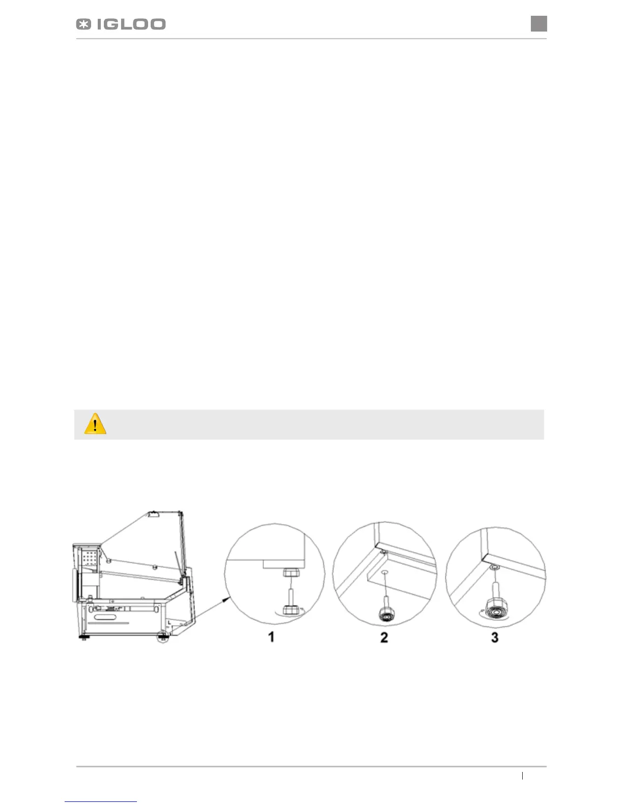
Fig.2 Removing the wooden platform
1 – Unscrew the feet from the platform
2 – Remove the wooden platform
3 – Screw the feet in nuts welded
to the frame of the device
3. PREPARING THE DEVICE FOR EXPLOITATION
3.1. Requirements concerning the place of installation
• Verify whether the cross section of feeding conduits is proper for power consumption of the installed device.
• It is forbidden to connect the device by extension rods or dividers.
• The device should be connected to the separate, properly made electric circuit with plug-in socket with protecting pin
(according to PBUE /Regulations concerning Electric Equipment Construction/)
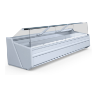
Fig.1 Construction of the device
1 – Granite working top
2 – Lamp
3 – Glass display shelf
4 – Front screen
5 – Display shelves (at; two-level; three-level)
6 – Front bumper
7 – Front
8 – Frame
9 – Storage chamber
10 – Rail (condensate outow after defrosting the evaporator)
11 – Evaporator
12 – Fish tank (“FISH” type)
13 – Evaporator in „Deep” devices
14 – Cooling aggregate
15 – Set of ventilators „Deep”
16 – GN containers (“GASTRO” type)
17 – Nameplate
18 – ABS sides
19 – Device levelling feet
20 – Ventilator (after removal access to condenser ns)
21 – Control panel (temperature regulator /switches)
22 – Storage chamber doors
3.2. Connection and actuation
• Unpack the device and remove the wooden platform from the basis (does not concern moving devices) Fig.2 (p.17