INSTALLER
USER
TECHNICIAN
10
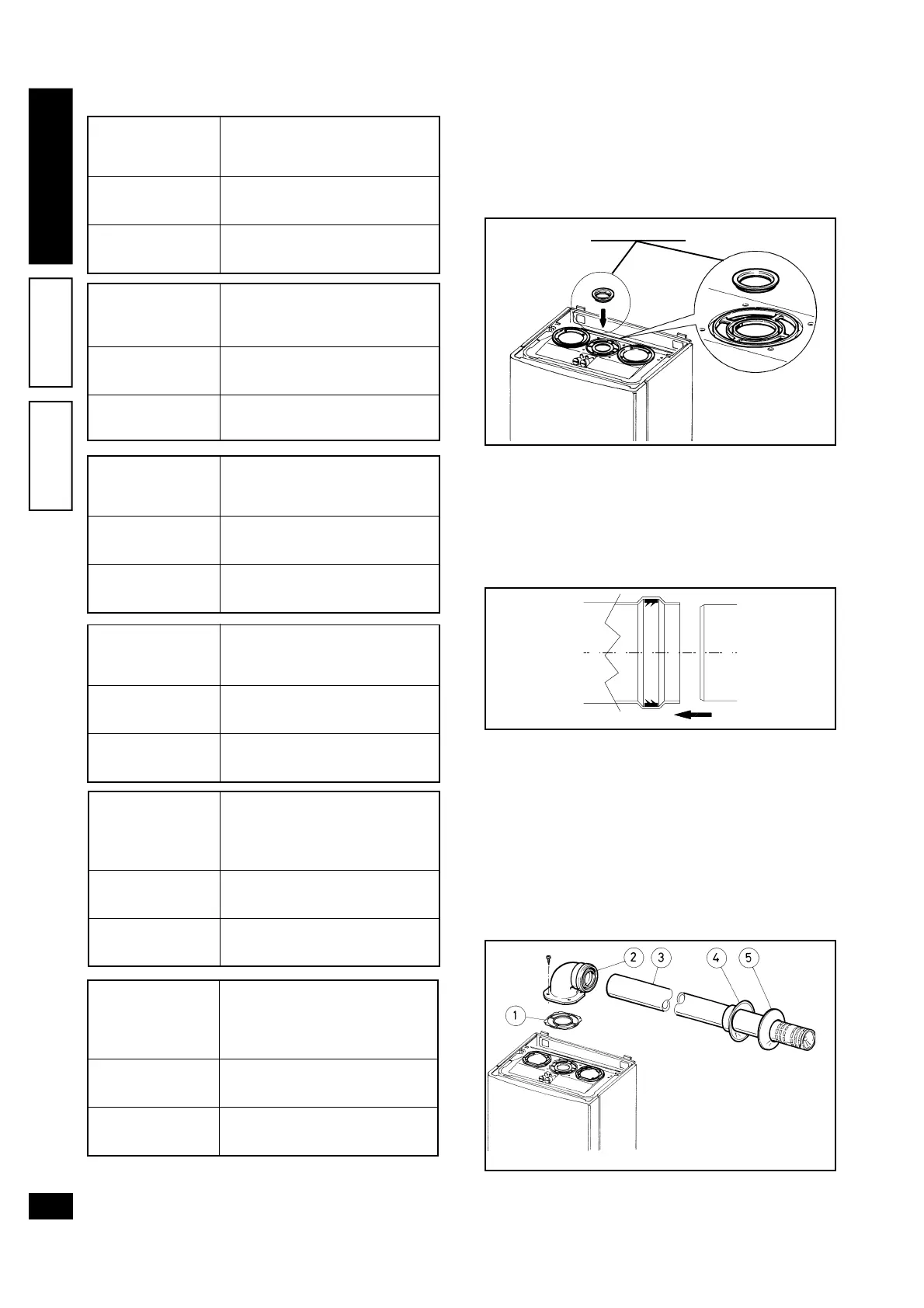
Diaphragm installation. To ensure correct opera-
tion of the boiler, a diaphragm (see figure) must be
installed on output of the sealed chamber before the
intake and exhaust duct. Selection of a suitable dia-
phragm depends on the type of ducting used and
maximum length: calculations can be made using
the values in the tables:
N.W.: Diaphragms are supplied as standard with the
boiler.
* The values for maximum length are considered with
1 metre of exhaust pipe and the remaining on in-
take.
Horizontal intake-exhaust kit Ø60/100. Kit assem-
bly: install the bend with flange (2) on the central
hole of the boiler taking care to insert the seal (1)
and secure by means of the screws supplied with
the kit. Join the male end (smooth section) of termi-
nal pipe (3) to the female section (with lip-seal) of
bend (2) to the end stop and ensure that the internal
and external washers are fitted to achieve perfect
sealing of all couplings.
• Snap-fit couplings of concentric pipes or extensions
and elbow fittings Ø60/100. To install extension
Eolo 27 Maior @ diaphragm table.
Ø 45
NONE
From 0 to 1
Over 1
DIAPHRAGM
Duct length in metres
Ø 60/100 horizontal
Ø 45
NONE
From 0 to 2,7
Over 2,7
DIAPHRAGM
Duct length in metres
Ø 60/100 vertical
Ø 45
NONE
From 0 to 1,9
Over 1,9
DIAPHRAGM
Duct length in metres
Ø 80/125 horizontal
Ø 45
NONE
From 0 to 6,8
Over 6,8
DIAPHRAGM
Duct length in metres
Ø 80/125 vertical
Ø 45
NONE
From 0 to 20
Over 20
DIAPHRAGM
*Duct length in metres
Ø 80 horizontal duct with two
bends
Ø 45
NONE
From 0 to 25
Over 25
DIAPHRAGM
*Duct length in metres
Ø 80 vertical duct without
bends
The kit comprises:
2 - Seal (1)
1 - Concentric 90° bend
(2)
1 - Intake/Exh. concentric
pipe Ø60/100 (3)
1 - Internal washer (4)
1 - External washer (5)
DIAPHRAGM
Positioning of double-lip seals. For correct posi-
tioning of the lip seals on elbows and extensions,
follow the order of assembly shown in the figure.