TECHNICIAN
INSTALLER
USER
11
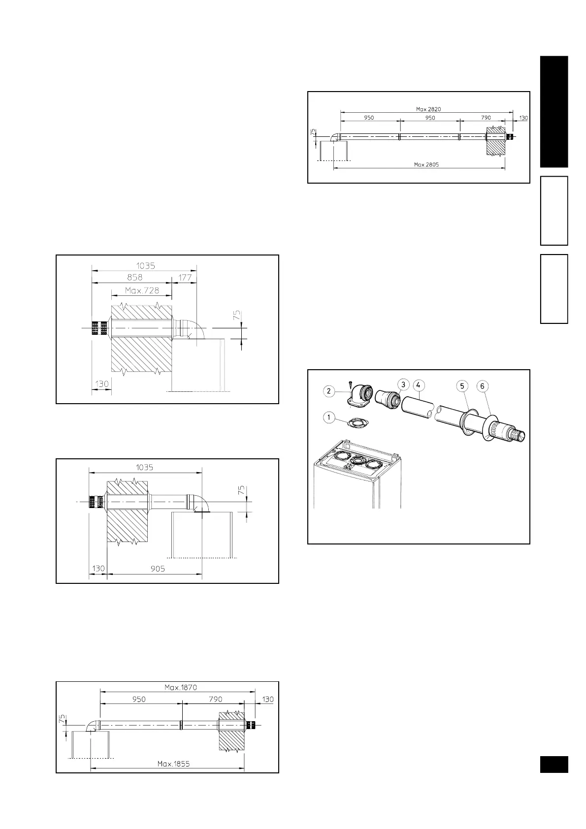
Connection with 1 extension. Max. distance be-
tween vertical boiler axis and external wall: 1855
mm.
Connection with 2 extensions. Max. distance be-
tween vertical boiler axis and external wall 2805.
Horizontal intake-exhaust kit Ø 80/125. Kit assem-
bly: install the bend with flange (2) on the central
hole of the boiler taking care to insert the seal (1)
and tighten with the screws supplied in the kit. Fit
the adapter (3) with the male section (smooth) in the
female section of the bend (2) (with lip seal) to the
end stop. Fit the concentric terminal Ø 80/125 (4)
with the male section (smooth) in the female section
of the adapter (3) (with lip seal) to the end stop, en-
suring that the internal and external washers are fit-
ted to ensure sealing efficiency of all couplings.
• Snap fit extension pipe fittings and concentric el-
bows Ø 80/125. To install snap-fit extensions with
other elements of the boiler assembly, proceed as
follows: fit the concentric pipe or elbow with the
male section (smooth) on the female section (with
lip seal) to the end stop on the previously installed
to ensure sealing efficiency of the coupling.
Caution: if the exhaust terminal and/or extension
concentric pipe needs shortening, consider that the
internal duct must always protrude by 5 mm with re-
spect to the external duct.
Normally the horizontal intake/exhaust kit Ø 80/125
is used in the event of using particularly long exten-
sions; the kit Ø 80/125 can be installed with a rear,
right-hand, left-hand or front outlet.
• Extensions for horizontal kit. The horizontal intake/
exhaust kit Ø 80/125 can be extended up to a
couplings on other flue extraction components, pro-
ceed as follows: fit the concentric pipe or concen-
tric elbow with the male section (smooth) on the
female section (with lip-seal) of the previously in-
stalled component to the end stop to ensure per-
fect sealing of the coupling.
The horizontal intake-exhaust kit Ø 60/100 can be
installed with a rear, right-hand, left-hand, or front
outlet as required.
• Application with rear outlet. The 970 mm pipe length
enables partial routing through a maximum thick-
ness 728 mm. Normally the terminal should be
shortened. Calculate the distance by adding the
following: Part thickness + internal protrusion + ex-
ternal protrusion. Minimum protrusion values are
given in the figure below.
• Application with lateral outlet; using the horizontal
intake-exhaust kit only, without the special
extensions, enables routing through a wall
thickness of 905 mm.
• Extensions for horizontal kit. The horizontal intake-
exhaust kit Ø 60/100 can be extended up to a max.
horizontal distance of 3000 mm including the grille
terminal and excluding the concentric bend on out-
put of the boiler. This configuration corresponds to
a resistance factor of 100. In this case special ex-
tensions must be requested.
The kit comprises:
2 - seal (1)
1 - Concentric bend
Ø 60/100 (2)
1 - Adapter Ø 60/100 for Ø
80/125 (3)
1 - Concentric Int./Exh.
bend Ø 80/125 (4)
1 - Internal washer (5)
1 - External washer (6)