INSTALLER
USER
TECHNICIAN
12
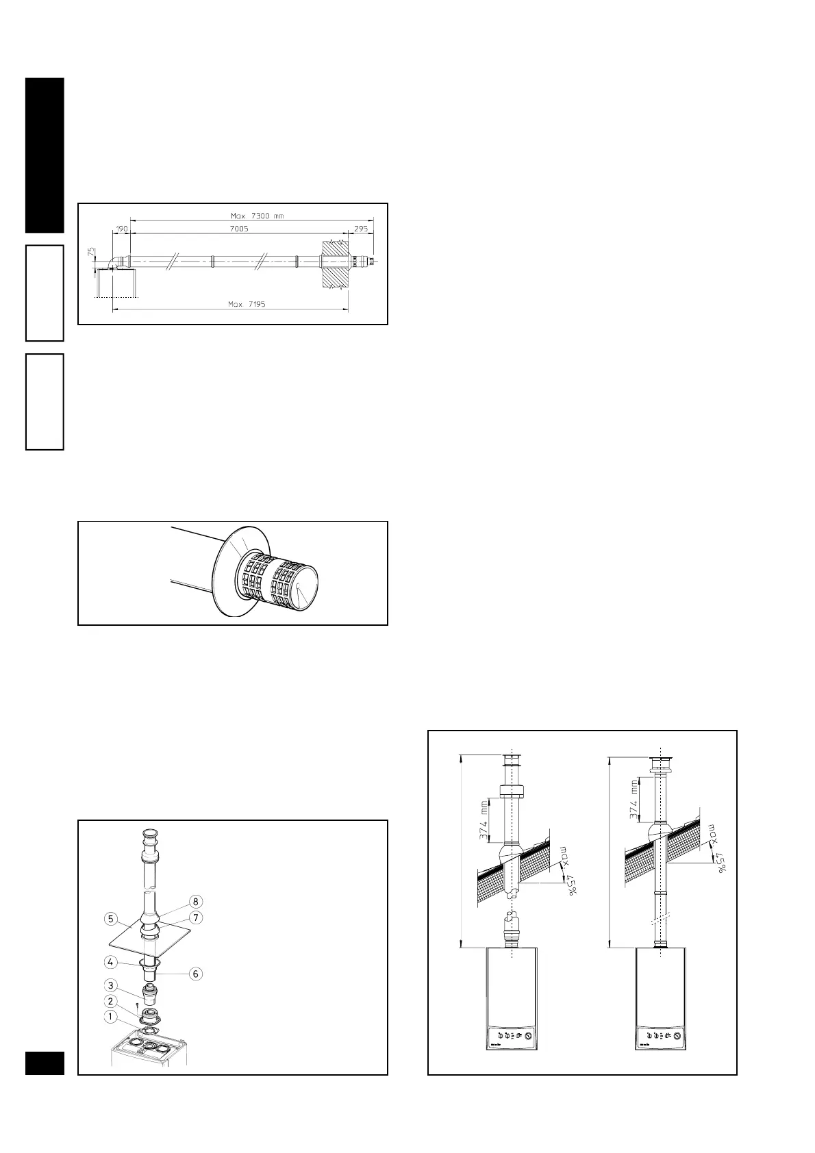
maximum horizontal length of 7300 mm including
the terminal grille and excluding the concentric
bend on output of the boiler and the adapter Ø 60/
100 in Ø 80/125 (see figure page 12). This con-
figuration corresponds to a resistance factor of
100. In these cases specific extensions must be
requested.
N.W.: when installing the ducts, a section clamp
with pin must be installed every 3 metres.
• External grille. The intake/exhaust terminal mod-
els Ø 60/100 and Ø 80/125, if correctly installed,
blend with external building aesthetics. Ensure that
the silicon washer is fitted snugly against the ex-
ternal wall.
N.W.: for safety purposes, do not totally or partially
obstruct the boiler intake/exhaust terminal even
temporarily.
Vertical kit with aluminium tile Ø 80/125. Kit as-
sembly: install the concentric flange (2) on the cen-
tral hole of the boiler taking care to insert the seal (1)
supplied with the kit and tighten by means of the
screws supplied with the boiler. Fit the male section
(smooth) of the adapter (3) coin the female section
of the concentric flange (2). Installing the imitation
aluminium tile. Replace the tile with the aluminium
sheet (5), shaping it to ensure off-flow of rainwater.
Position the fixed half-shell (7) on the aluminium tile
and insert the intake/exhaust pipe (6). Fit the con-
centric terminal Ø 80/125 with the male section (6)
(smooth), in the female section of the adapter (3)
(with lip seal) to the end stop, ensuring that washer
(4) si already fitted to ensure sealing efficiency of all
couplings.
• Snap fit extension pipe fittings and concentric el-
bows Ø 80/125. To install snap-fit extensions with
other elements of the boiler assembly, proceed as
follows: fit the concentric pipe or elbow with the
male section (smooth) on the female section (with
lip seal) to the end stop on the previously installed
to ensure sealing efficiency of the couplings.
Caution: if the exhaust terminal and/or extension
concentric pipe needs shortening, consider that the
internal duct must always protrude by 5 mm with re-
spect to the external duct.
This specific terminal enables flue exhaust and air
intake in a vertical direction.
N.W.: the vertical kit Ø 80/125 with aluminium tile
enables installation on terraces and roofs with maxi-
mum gradient of 45% (24°) and the height between
the terminal cap and half-shell (374 mm) must be
strictly observed.
This vertical kit configuration can be extended to a
maximum length of 12200 mm in a vertical straight
route, including the terminal (see figure below). This
configuration corresponds to a resistance factor of
100. In this case specific extensions must be re-
quested.
Terminal Ø 60/100 can also be used for vertical ex-
haust, in conjunction with concentric flange code no.
3.011141 (sold separately). height between the ter-
minal cap and half-shell (374 mm) must be strictly
observed (see drawing below).
This vertical kit configuration can be extended to a
maximum length of 4700 mm in a vertical straight
line, including the terminal (see figure below).
MAX. LENGTH 4700 mm
MAX. LENGTH 12200 mm
The kit comprises:
2 - Seal (1)
1 - Female concentric flange
(2)
1 - Adapter Ø 60/100 for Ø
80/125 (3)
1 - Washer(4)
1 - Aluminium tile (5)
1 - Int./Exh. concentric pipe
Ø 80/125 (6)
1 - Fixed half-shell (7)
1 - Mobile half-shell (8)