TECHNICIAN
INSTALLER
USER
13
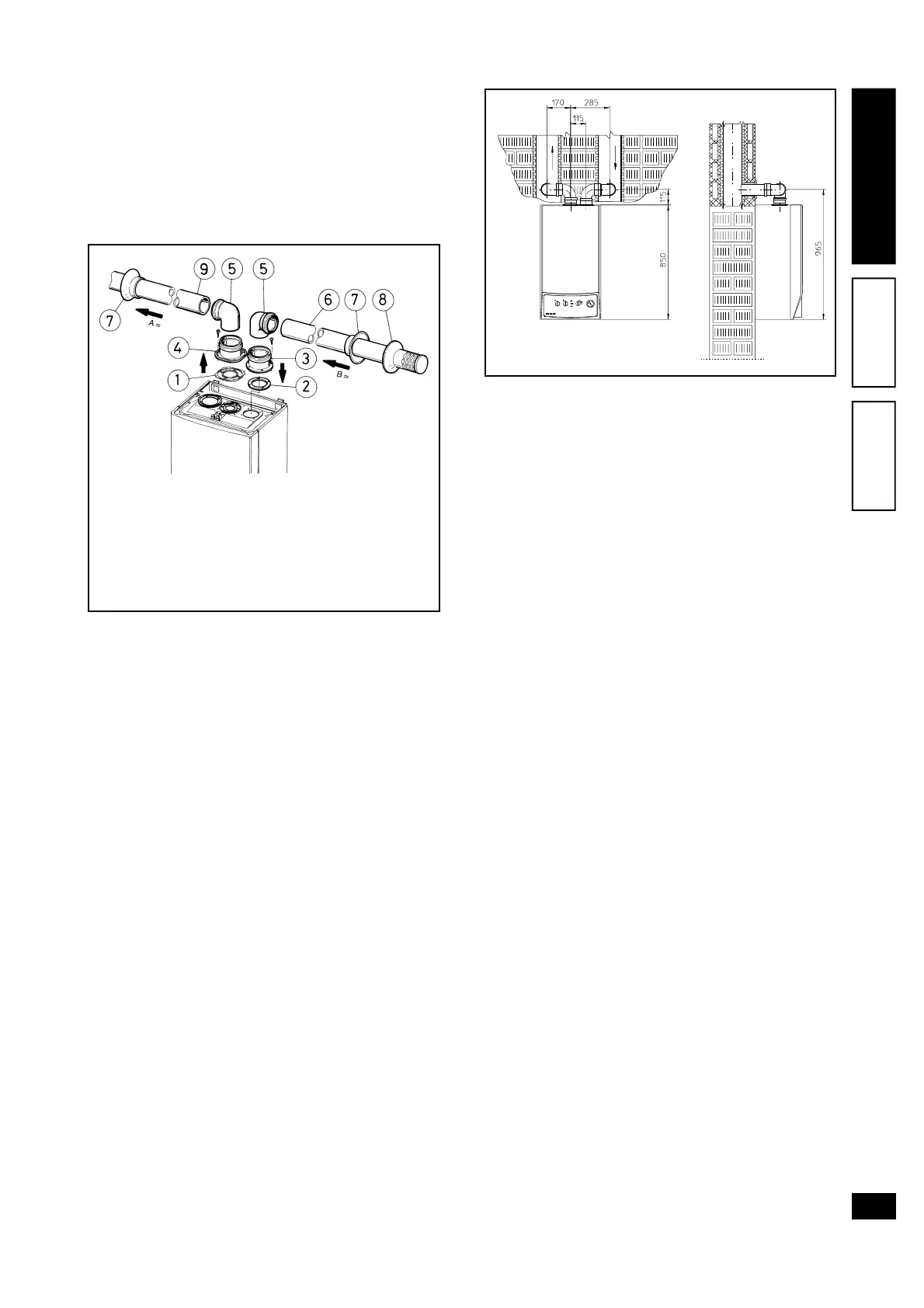
Separator kit Ø 80/80. The separator kit Ø 80/80,
enables the division of the flue exhaust pipes and air
intake pipes according to the diagram shown in the
figure. Combustion products are expelled from duct
(A). Air is taken in through duct (B) for combustion.
Intake duct (B) can be installed either on the right or
left hand side of the central exhaust duct (A). Both
ducts can be routed in any direction.
• Assembly of separator kit Ø 80/80. Install flange
(4) on the central hole of the boiler taking care to
insert seal (1) supplied with the kit and tighten by
means of the screws on the boiler. Remove the
flat flange on the lateral hole (depending on instal-
lation requirements) and replace with flange (3)
inserting seal (2) already fitted on the boiler and
tighten with the screws supplied. Joins bends (5)
with the male section (smooth) in the female section
of the flanges (3 and 4). Fit the intake terminal (6)
with the male section (smooth) in the female section
of the flange (5) to the end stop with the internal
and external washers inserted. Join the exhaust
pipe (9) with the male section (smooth) in the
female section of the bend (5) to the end stop
ensuring that the internal washer is fitted and to
ensure sealing efficiency of the couplings.
• Snap fit extension pipe fittings and elbows. To in-
stall snap-fit extensions with other elements of the
boiler assembly, proceed as follows: fit the pipe or
elbow with the male section (smooth) on the fe-
male section (with lip seal) to the end stop on the
previously installed to ensure sealing efficiency of
the couplings.
• Installation clearances. The following figure shows
the minimum installation clearances for the termi-
nal separator kit Ø 80/80 in maximum admissible
conditions.
• Extension for separator kit Ø 80/80. The maximum
straight length (without bends) on a vertical route,
for intake and exhaust pipes Ø80 is 41 metres, 40
of which on intake and 1 on exhaust. This total
length corresponds to a resistance factor of 100.
The total effective length, obtained by adding the
length of intake and exhaust pipes Ø 80 must not
exceed the maximum values specified in the table
below. If mixed accessories or components are
used (e.g. changing from a separator Ø 80/80 to a
concentric pipe), the maximum extension can be
calculated by using the resistance factor for each
component or the equivalent length. The total of
the resistance factors must not exceed 100.
• Temperature drops in flue ducts. To avoid the prob-
lem of flue condensation in the exhaust pipe Ø 80,
due to cooling through the walls, the length of the
duct must be restricted to within 5 metres. If longer
distances have to be covered, use pipe diameters
Ø 80 with insulation (see insulated separator kit Ø
80/80).
The kit comprises:
2 Seal (1)
1 - Female intake
flange (3)
1 - Flange seal (2)
1 - Female exhaust
flange (4)
2 - 90° bend Ø 80 (5)
1 - Intake terminal Ø 80
(6)
2 - Internal washers (7)
1 - External washer (8)
1 - Exhaust pipe Ø 80 (9)
A = EXHAUST
B= INTAKE