7
45
31
58
6
14
INSTALLER
USER
MAINTENANCE TECHNICIAN
TECHNICAL DATA
• Comando Amico Remoto
V2
Remote Control Device (CAR
V2
)
with climate timer thermostat function.
In addition to the functions described in the previous point,
the CAR
V2
panel enables the user to control all the important
information regarding operation of the appliance and the heating
system with the opportunity to easily intervene on the previously
set parameters, without having to go to where the appliance is
installed. e panel is provided with self-diagnosis to display
any boiler functioning anomalies. e climate chrono-thermo-
stat incorporated into the remote panel enables the system ow
temperature to be adjusted to the actual needs of the room being
heated, in order to obtain the desired room temperature with
extreme precision and therefore with evident saving in running
costs.
if the system is subdivided into zones using the relevant
kit. the CAR
V2
must be used with its climate thermostat
function disabled, i.e. it must be set to On/O mode
CAR
V2
or chrono-thermostat On/Off electric connection
(Optional). e operations described below must be performed
aer having removed the voltage from the appliance. Any On/O
room chrono-thermostat must be connected to clamps 40 and
41 eliminating jumper X40 (Fig. 36). Make sure that the On/O
thermostat contact is of the “clean” type, i.e. independent of the
mains voltage, otherwise the P.C.B. would be damaged. Any CAR
V2
must be connected to clamps 40 and 41 eliminating jumper X40
on the circuit board, paying attention not to invert the polarity in
the connections (Fig. 36).
If the CAR
V2
remote control or any other On/O
chronothermostat is used, arrange two separate lines
in compliance with current regulations regarding
electrical systems. No boiler pipes must ever be used to
earth the electric system or telephone lines. Ensure elimination
of this risk before making the boiler electrical connections.
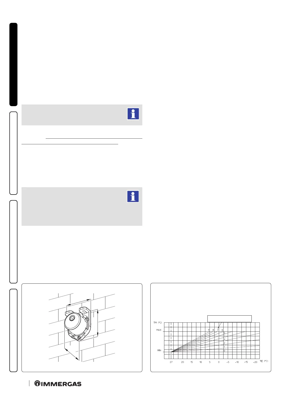
EXTERNAL PROBE
Correction law of the ow temperature depending on the external
temperature and user adjustment of the central heating temperature.
Position of the central heating
temperature user adjustment
1.10 External temperature probe (Optional).
e boiler is designed for the application of the external temper-
ature probe (Fig. 6), which is available as an optional kit. Refer to
the relative instruction sheet for positioning of the external probe.
The probe can be connected directly to the boiler electrical
system and allows the max. system ow temperature to be au-
tomatically decreased when the external temperature increases,
in order to adjust the heat supplied to the system according to
the change in external temperature. e external probe always
operates when connected, regardless of the presence or type of
room chrono-thermostat used and can work in combination with
Immergas chrono-thermostats. e correlation between system
ow temperature and external temperature is determined by the
position of the central heating selector switch on the boiler control
panel (or on the CAR
V2
control panel if connected to the boiler)
according to the curves shown in the diagram (Fig. 7). e electric
connection of the external probe must be made on clamps 38 and
39 on the terminal board in the boiler control panel (Fig. 36).