35
38
INSTALLER
USER
MAINTENANCE TECHNICIAN
TECHNICAL DATA
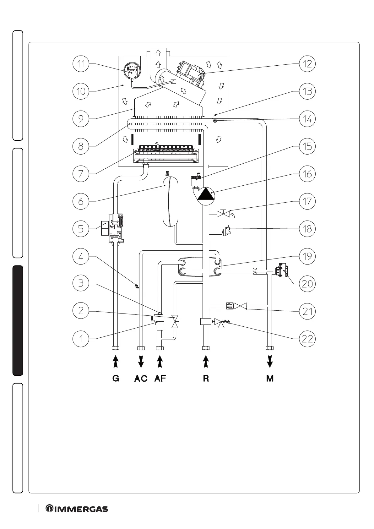
3.4 Boiler Hydraulic diagram.
Key:
1 - Domestic hot water ow switch
2 - System lling valve
3 - Flow limiter
4 - Domestic hot water probe
5 - Gas valve
6 - System expansion vessel
7 - Burner
8 - Primary heat exchanger
9 - Fumes hood
10 - Sealed Chamber
11 - Flue pressure switch
12 - Fan
13 - Delivery probe
14 - Safety thermostat
15 - Vent valve
16 - Boiler pump
17 - System draining valve
18 - System pressure switch
19 - Plate heat exchanger
20 - ree-way valve (motorised)
21 - By-pass
22 - 3 bar safety valve
G - Gas supply
AC - Domestic hot water outlet
AF - Domestic hot water inlet
R - System return
M - System ow