31
0 200 400 600 800 1000 1200 1400 1600
Y1
20
40
60
10
30
50
0
20
40
60
10
30
50
0
1
2
3
4
27
INSTALLER
USER
MAINTENANCE TECHNICIAN
TECHNICAL DATA
1.22 Circulation pump.
e boilers are supplied with a built-in circulation pump with
three-position electric speed control. e boiler does not oper-
ate correctly with the circulation pump on rst speed. To ensure
optimal boiler operation, in the case of new systems (single pipe
and module) it is recommended to use the pump at maximum
speed. e circulation pump is already tted with a condenser.
Pump release. If, aer a prolonged period of inactivity, the circu-
lation pump is blocked, unscrew the front cap and turn the motor
sha using a screwdriver. Take great care during this operation to
avoid damage to the motor.
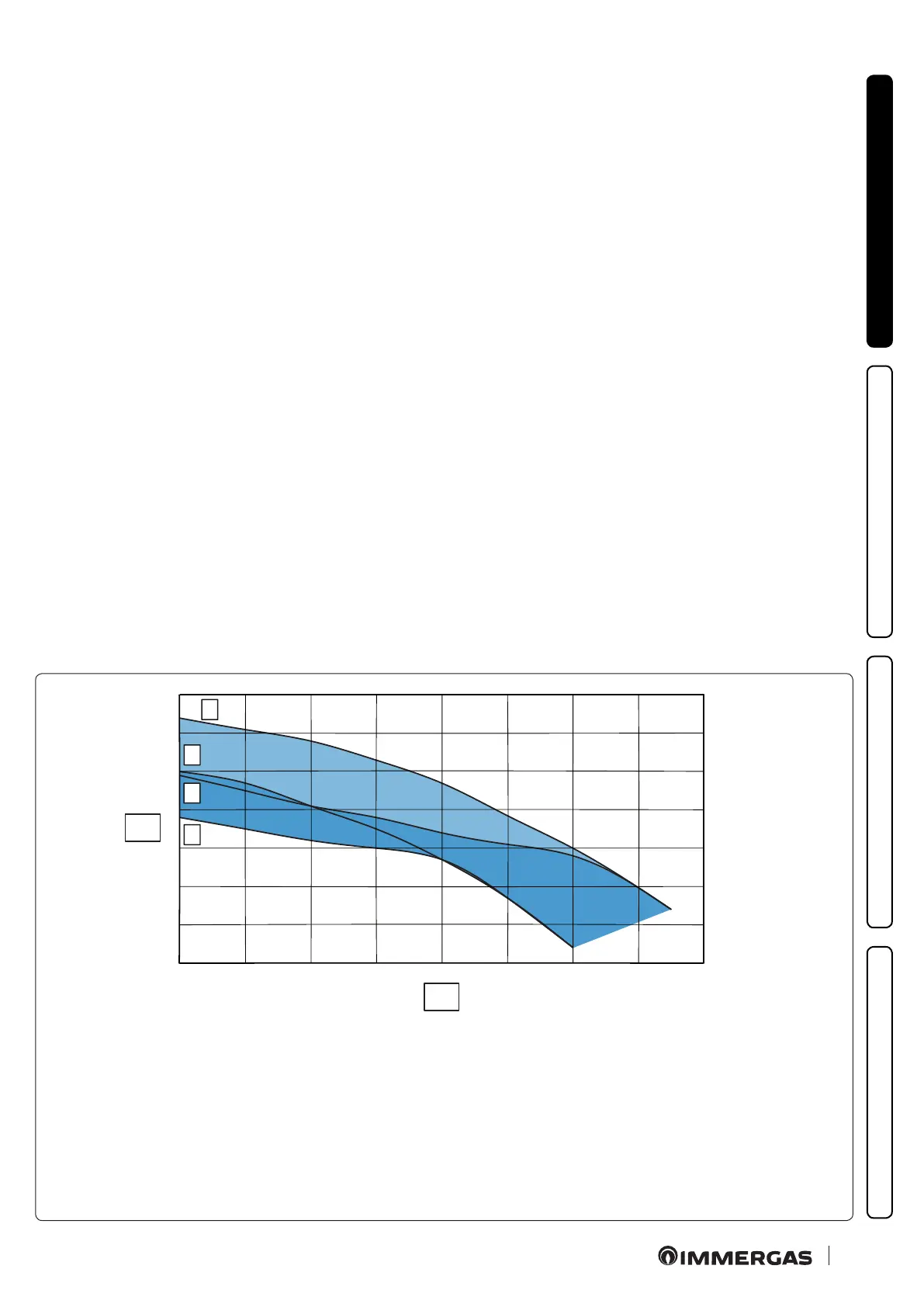
By-pass adjustment (Part. 25 Fig. 32). If necessary, the by-
pass can be adjusted according to system requirements from a
minimum (by-pass excluded) to a maximum (by-pass inserted)
represented by the graph (Fig. 31). Make the adjustment using a
at head screwdriver, turn clockwise and insert the by-pass; by
turning it anti-clockwise it is excluded.
Head available to the system.
1.23 Kits available on request.
• System shut o valves kit. e boiler is designed for installation
of system interception cocks to be placed on ow and return
pipes of the connection assembly. is kit is particularly useful
for maintenance as it allows the boiler to be drained separately
without having to empty the entire system.
• Polyphosphate dispenser kit. e polyphosphate dispenser re-
duces the formation of lime-scale and preserves the original heat
exchange and domestic hot water production conditions. e
boiler is prepared for application of the polyphosphate dispenser
kit.
• Cover kit. For outdoor installations, in partially protected areas
and with direct air intake, the top protection cover must be tted
for a correct functioning of the boiler and to protect it from
storms (Fig. 9). For indoor installations, type B conguration, a
suitable top protection cover coupled with the ue exhaust kit
must be tted.
• Anti freeze kit with resistance (on request). If the boiler is in-
stalled in a place where the temperature falls below -5°C and in
the event there is no gas, the appliance can freeze. To prevent
freezing of the domestic hot water system, an anti freeze kit with
an electrical resistance can be tted from the relative cable and
from a control thermostat.
e above-mentioned kits are supplied complete with instructions
for assembly and use. Check the complete list of kits available and
which can be combined with the product, consult the Immergas
website, the Immergas Price List or the technical-commercial
documentation (catalogues and data sheets).
Key:
1 = Head available to the system at speed 3 with by-pass closed
2 = Head available to the system at speed 3 with by-pass open
3 = Head available to the system at speed 2 with by-pass closed
4 = Head available to the system at speed 2 with by-pass open
Area between curves 1 and 3 = Available system head with by-pass closed
Area between curves 2 and 4 = Available system head with by-pass open
X1 = Flow rate (l/h)
Y1 = Head (kPa)