47
INSTALLER
USERMAINTENANCE TECHNICIAN
TECHNICAL DATA
4
TECHNICAL DATA.
4.1 Variable heat output.
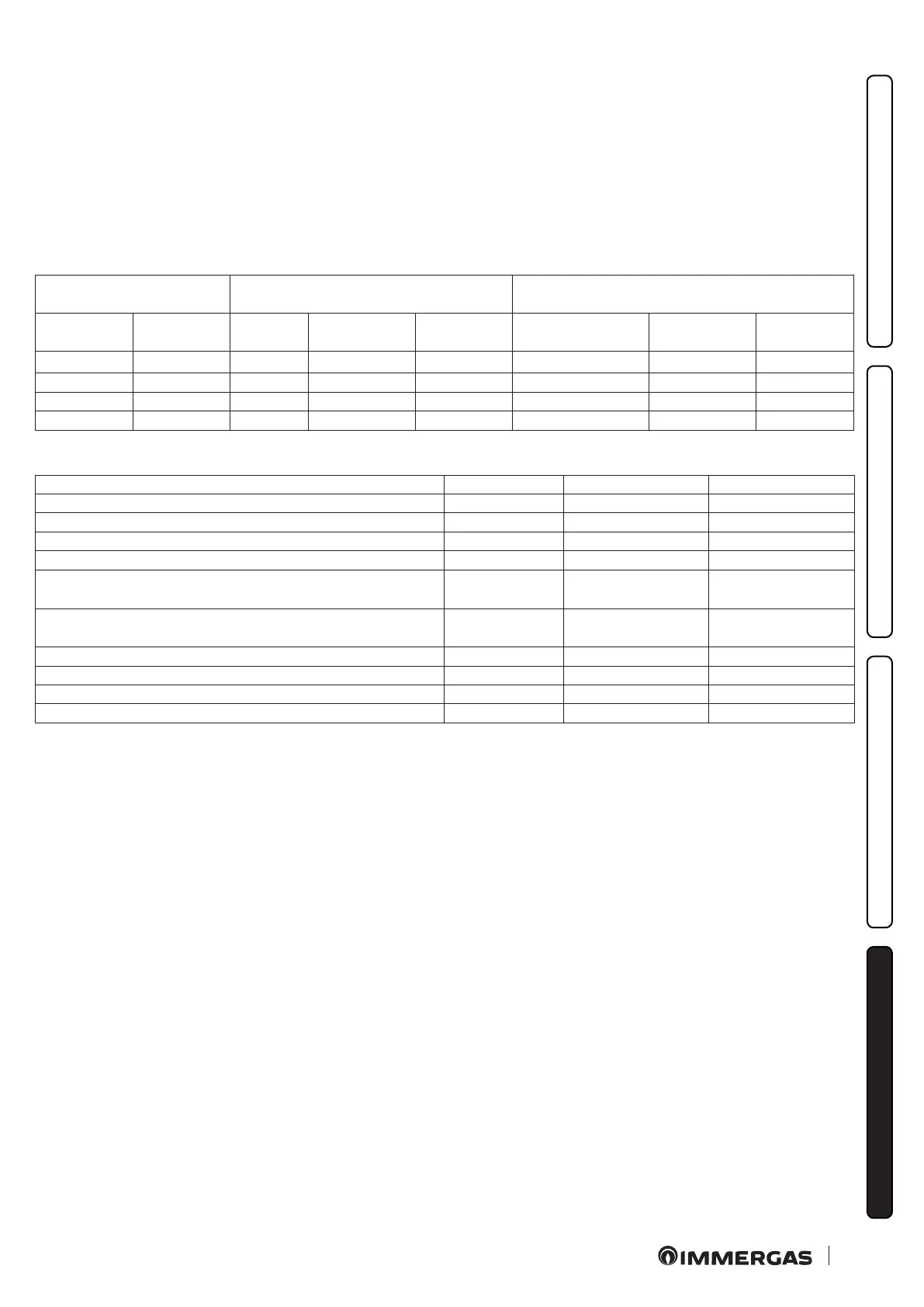
N.B.: the pressures indicated in the tables represent the dierence
in existing pressures between the gas valve outlet and the com-
bustion chamber. e adjustments should therefore,be carried
out using a dierential manometer (small "U"-shaped column
or digital manometer) with the probes inserted in the pressure
test gas valve outlet and on the sealed chamber positive pressure
test. e power data given in the table is obtained with 0.5m long
intake/exhaust pipe. Gas ow rates refer to heating power below a
temperature of 15°C and pressure of 1013 mbar. Burner pressure
values refer to use of gas at 15°C.
4.2 COMBUSTION PARAMETERS.
G20 G31
Gas nozzle diameter mm 1.35 0.78
Supply pressure mbar (mm H
2
O) 20 (204) 37 (377)
Flue ow rate at heating nominal heat output kg/h 62 64
Flue ow rate at min heat output kg/h 66 64
CO
2
at Nominal Q.
O
2
at Nominal Q.
%
6.9
8.5
7.6
-
CO
2
to minimum Q.
O
2
to minimum Q.
%
2.6
16.2
3.1
-
CO at 0% of O
2
at Nom. Q./Min. ppm 105 / 109 106 / 128
NO
X
at 0% of O
2
at Nom.Q./Min. mg/kWh 211.0 / - 302.0 / 173.0
Flue temperature at nominal output °C 128.0 128
Flue temperature at minimum output °C 106 104
METHANE
(G20)
PROPANE
(G31)
HEAT
INPUT
HEAT
OUTPUT
FAN R EVS MODULATION
BURNER GAS
FLOW RATE
FAN R EVS MODULATION
BURNER GAS
FLOW RATE
(kW) (kW) (rpm) (%) (m
3
/h) (rpm) (%) (kg/h)
29.7 27.6 11.3 100 3.14 36 100 2.31
12.7 11.0 2.3 7 1.34 7.8 9 0.99
9.9 8.6 1.6 0 1.05 5 0 0.77