8 9
15
INSTALLER
USER
MAINTENANCE TECHNICIAN
TECHNICAL DATA
1.11 Immergas ue systems.
Immergas supplies various solutions separately from the boilers
regarding the installation of air intake terminals and ue exhaust,
which are fundamental for boiler operation.
ATTENTION:
the boiler must only be installed togeth-
er with an original Immergas air intake
and ue gas exhaust system.
is ue can be identied by an identication
mark and special distinctive marking bearing
the note "not for condensing boilers".
e ue exhaust pipes must not be in contact
with or be near to ammable materials. More-
over, they must not pass through buildings or
walls made of ammable material.
See following paragraphs for the detailed description of the kits
available
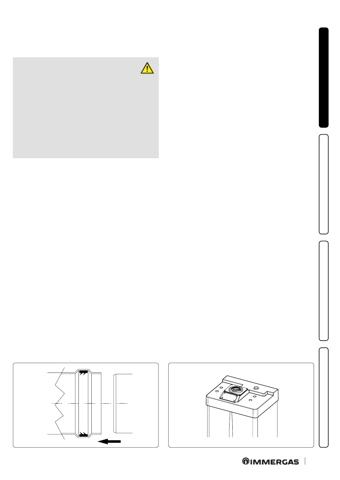
• Positioning of double lip seals.
For correct positioning of lip seals on elbows and extensions,
follow the direction of assembly given in gure (Fig. 8).
• Resistance factors and equivalent lengths.
Each ue component has a Resistance Factor based on exper-
imental tests and specied in the table below. e Resistance
Factor for individual components is independent from the type
of boiler on which it is installed and has a dimensionless size. It
is however, conditioned by the temperature of the uids that pass
through the pipe and therefore, varies according to applications
for air intake or ue exhaust. Each single component has a resist-
ance corresponding to a certain length in metres of pipe of the
same diameter; the so-called equivalent length, can be obtained
from the ratio between the relative Resistance Factors.
All boilers have an experimentally obtainable maximum Re-
sistance Factor equal to 100.
e maximum Resistance Factor allowed corresponds to the
resistance encountered with the maximum allowed pipe length
for each type of Terminal Kit. is information allows calcula-
tions to be made to verify the possibility of setting up various
ue congurations.