38
1
3
3
2
a
b
b
c
45
INSTALLER
USER
MAINTENANCE TECHNICIAN
TECHNICAL DATA
3.16 SOLAR PANELS COUPLING FUNCTION.
e boiler is set-up to receive pre-heated water from a system of
solar panels up to a maximum temperature of 65°C. In all cases, it
is always necessary to install a mixing vale on the hydraulic circuit
upstream from the boiler on the cold water inlet.
For good functioning of the boiler; the temperature
selected on the solar valve must be 5°C greater with
respect to the temperature selected on the boiler
control panel.
For correct use of the boiler in this condition, parameter P3 (DHW
thermostat) must be set at “1” and the parameter P9 (Solar mode
(DHW ignition delay.) at a temperature sucient to receive water
from a storage tank situated upstream from the boiler. e greater
the distance from the storage tank, the longer the stand-by time
to be set. When these regulations have been performed, when
the boiler inlet water is at the same or greater temperature with
respect to that set by the DHW selector switch, the boiler does
not switch on.
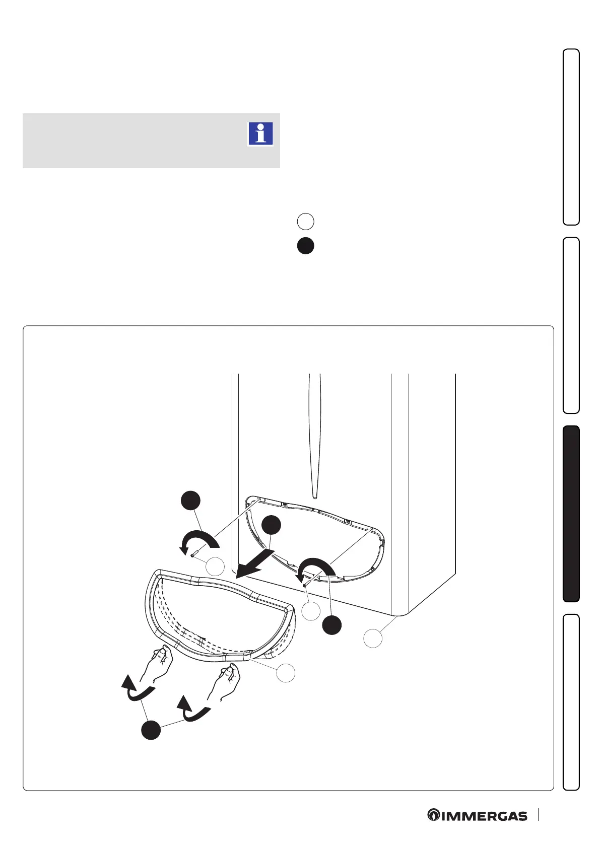
3.17 C A S I N G R E M OVA L .
To facilitate boiler maintenance the casing can be completely
removed as follows (Fig. 38 / 39):
1 Unhook the decorative frame (a) from the relative lower re-
tainers.
2 Remove the decorative frame (a) from the casing (c).
3 Loosen the 2 front screws (b) for xing the casing.
4 Pull the case towards yourself (c).
5 Push the case (c) upwards at the same time to release it from
the upper hooks.
Installation drawings key:
a
Unmistakeable component identication
1
Sequential identication of the operation to perform