36
5
1
2
6
5
4
3
4
4
5
11
7
7
7
12
12
7
13
13
11
4
5
5
7
4
10
10
10
10
9
8
39
INSTALLER
USER
MAINTENANCE TECHNICIAN
TECHNICAL DATA
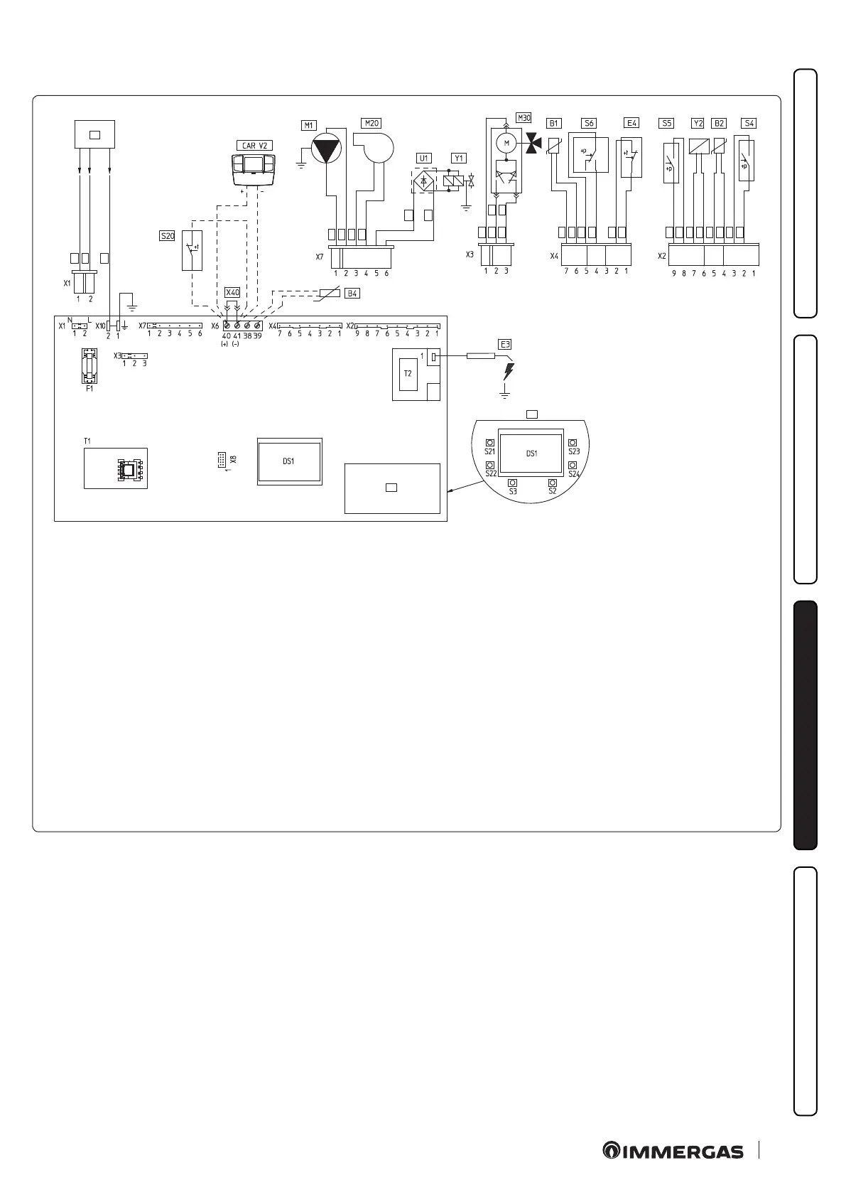
3.5 Wiring diagram.
Key:
B1 - Flow probe
B2 - Domestic hot water probe
B4 - External probe
CAR
V2
- Comando Amico Remoto
V2
remote control Version 2 (optional)
DS1 - Display
E3 - Ignition and detection electrodes
E4 - Safety thermostat
F1 - Phase fuse
M1 - Boiler pump
M20 - Fan
M30 - ree-way valve
S2 - Selector switch functioning
S3 - Reset block keys
S4 - Domestic hot water ow switch
S5 - System pressure switch
S6 - Flue gas pressure switch
S20 - Room thermostat (optional)
S21 - Domestic hot water temperature
increase key
S22 - Domestic hot water temperature
reduce key
S23 - Heating temperature increase key
S24 - Heating temperature
reduce key
T1 - Low voltage feeder
T2 - Switch-on transformer
U1 - Rectier inside the gas valve con-
nector (Only available
on Honeywell gas valves)
X40 - Room thermostat jumper
Y1 - Gas valve
Y2 - Gas valve modulator
1 - User interface
2 - N.B.: e user interface is on the
welding side of the boiler board
3 - 230 Vac 50Hz power supply
4 - Blue
5 - Brown
6 - Yellow/Green
7 - Black
8 - (DHW)
9 - (central heating)
10 - Grey
11 - White
12 - Red
13 - Green
e boiler is designed for application of a room thermostat (S20),
an On/O room chronothermostat, a program timer or a Coman-
do Amico Remoto
V2
remote control (CAR
V2
). Connect to clamps
40 - 41 eliminating the jumper X40, paying attention not to invert
the polarity if the CAR
V2
is installed.
e connector X8 is used for the connection of the Virgilio Palm-
top in the microprocessor soware updating operation.