12
13
17
INSTALLER
USER
MAINTENANCE TECHNICIAN
TECHNICAL DATA
• Conguration without cover kit (boiler typeC).
By leaving the side plugs tted, it is possible to install the appli-
ance externally, in partially covered places, without the cover
kit. Installation takes place using the Ø60/100 and Ø80/125
concentric horizontal intake/ exhaust kits. Refer to the para-
graph relative to indoor installation. In this conguration the
top cover kit guarantees additional protection for the boiler. It
is recommended but not compulsory.
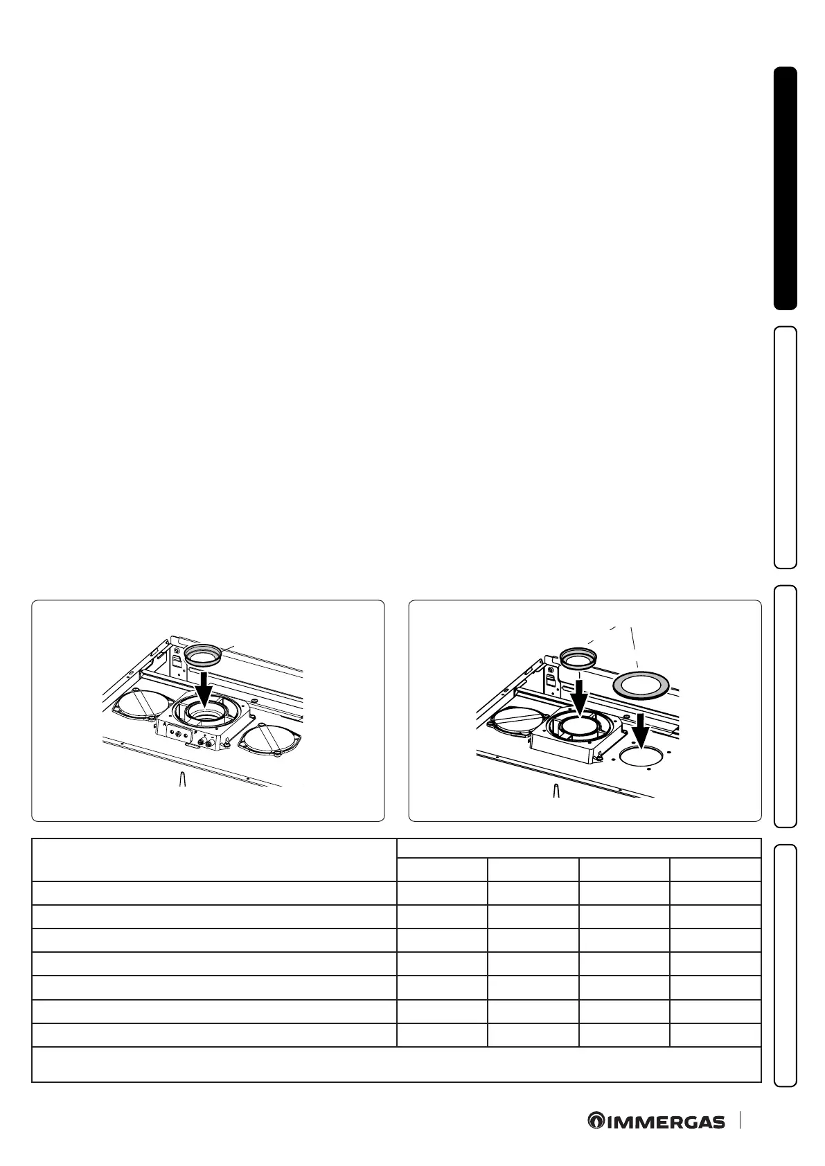
• Diaphragm installation.
For correct functioning of the boiler it is necessary to install a
diaphragm on the outlet of the sealed chamber and before the
intake and exhaust pipe (Fig. 12).
e choice of suitable diaphragm takes place on the basis of the
type of pipe and its maximum extension: this calculation can be
carried out using the following tables:
N.B.: the diaphragms are supplied together with the boiler.
Type of installation
(duct length in metres)
Diaphragm
Ø 38 Ø 40 Ø 42,5
WITHOUT
Ø60/100 horizontal concentric kit From 0 to 0.5 From 0.5 to 1.5 - From 1.5 to 3.0
Ø60/100 vertical concentric kit From 0 to 2.2 From 2.2 to 3.7 - From 3.7 to 4.7
Ø80/125 horizontal concentric kit From 0 to 0.5 From 0.5 to 4.6 - From 4.6 to 7.4
Ø80/125 vertical concentric kit From 0 to 5.4 From 5.4 to 9.5 - From 9.5 to 12.2
Ø80 vertical separator kit without bends *From 0 to 20 *From 20 to 40 **From 0 to 22 ** From 22 to 33
Ø80 horizontal separator kit with two bend *From 0 to 16 *From 16 to 35 **From 0 to 17 ** From 17 to 28
Direct intake kit and Ø80 drain in B
22
conguration From 0 to 0.5 - From 0.5 to 15 -
* ese maximum extension values are considered intake with 1 metre drain pipe
** ese maximum extension values are considered in draining with 1 metre intake pipe and Ø 47 diaphragm on the intake hole.
DIAPHRAGM
Exhaust
Intake
• Intake diaphragm installation.
For correct boiler functioning with Ø 80 separator kits and
drain measuring > 1 m a diaphragm Ø 47 must be installed on
the sealed chamber intake hole and before the intake pipe (Fig.
13). e choice of suitable diaphragm takes place on the basis
of the type of pipe and its maximum extension: this calculation
can be carried out using the following tables:
DIAPHRAGM