84
RO SKIE
3-2
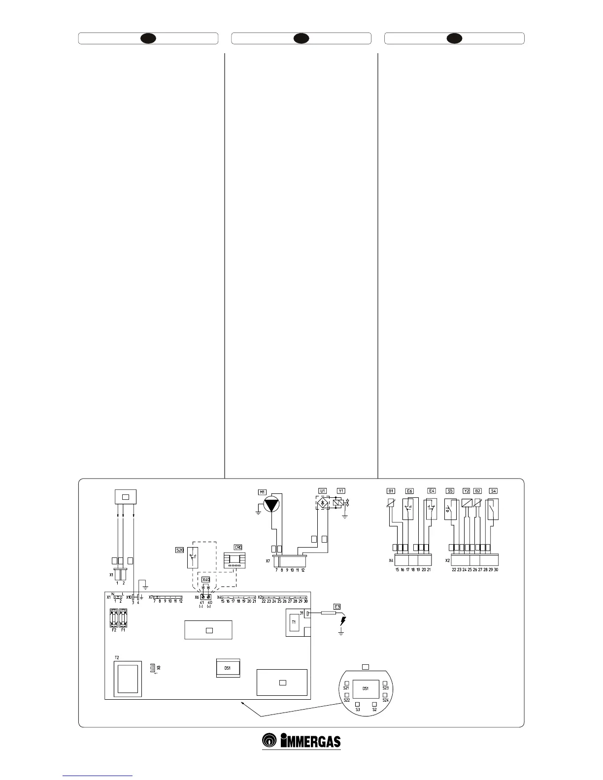
Legenda (Fig. 3-2):
B1 - Sondă tur
B2 - Sondă menajer
CRD - Comandă de la Distanţă Digitală
(opţional)
DS1 - Display
E3 - Bujie de pornire şi indicare
E4 - Termostat siguranţă
F1 - Siguranţă linie
F2 - Siguranţă nul
M1 - Circulator cazan
M20 - Ventilator
S2 - Selector funcţionare
S3 - Buton resetare blocare
S4 - Fluxostat menajer
S5 - Presostat instalaţie
S20 - Termostat ambient (opţional)
S21 - Buton creştere temperatură apă menajeră
S22 - Buton scădere
temperatură apă menajeră
S23 - Buton creştere temperatură încălzire
S24 - Buton descreştere temperatura încălzire
T1 - Transformator pornire
T2 - Transformator placă centrală
U1 - Redresor intern la conector supapă gaz
(prezent doar pe valve gaz Honeywell)
X40 - Punte termostat ambient
Y1 - Supapă gaz
Y2 - Modulator supapă gaz
1 - Interfaţă utilizator
2 - N.B.: interfaţă utilizator se aă pe latura
suduri ale plăcii centralei
3 - Conectorul X6 e utilizat pentru calibra-
rea automată
4 - Alimentare 230 Vac 50Hz
5-Albastru
6-Maro
7 - Galben / Verde
8-Negru
9-Gri
10 - Alb
11 - Roşu
Key (Fig. 3-2):
B1 - Delivery probe
B2 - Domestic hot water probe
DRC - Digital Remote Control (optional)
DS1 - Display
E3 - Ignition and detection electrodes
E4 - Safety thermostat
F1 - Phase fuse
F2 - Neutral fuse
M1 - Boiler circulating pump
S2 - Selector switch functioning
S3 - Reset block keys
S4 - Domestic hot water ow switch
S5 - System pressure switch
S20 - Room thermostat (optional)
S21 - Domestic hot water temperature increase
key
S22 - Domestic hot water temperature reduce
key
S23 - Heating temperature increase key
S24 - Heating temperature reduce key
T1 - Switch-on transformer
T2 - Boiler board transformer
U1 - Rectier inside the gas valve connector
(Only available on Honeywell gas valves)
X40 - Room thermostat jumper
Y1 - Gas valve
Y2 - Gas valve modulator
1 - User interface
2 - N.B.: e user interface is on the welding
side of the boiler board
3 - e X6 connector is used for automatic
inspection
4 - 230 Vac 50Hz power supply
5-Blue
6-Brown
7 - Yellow/Green
8-Black
9-Grey
10 - White
11 - Red
Legenda (Obr. 3-2):
B1 - Sonda výtlaku
B2 - Úžitková sonda
CRD - Diaľkové ovládanie Comando remoto
digitale (voliteľne)
DS1 - Displej
E3 - Zapaľovacie a detekčné sviečky
E4 - Bezpečnostný termostat
F1 - Poistka el. vedenia
F2 - Neutrálna poistka
M1 - Obehové čerpadlo kotla
S2 - Volič prevádzky
S3 - Tlačidlo reset linky
S4 - Prietokomer úžitkovej vody
S5 - Presostat zariadenia
S20 - Izbový termostat (voliteľne)
S21 - Tlačidlo zvýšenia teploty úžitkovej vody
S22 - Tlačidlo zvýšenia teploty úžitkovej vody
S23 - Tlačidlo zvýšenia teploty vykurovania
S24 - Tlačidlo zníženia teploty vykurovania
T1 - Transformátor zapínania
T2 - Transformátor karty kotla
U1 - Vnútorný usmerňovač konektoru plyno-
vého ventilu (len u plynových ventilov
Honewell)
X40 - Most izbového termostatu
Y1 - Plynový ventil
Y2 - Modulátor plynového ventilu
1 - Užívateľské rozhranie
2 - Poznámka: užívateľské rozhranie sa
nachádza na strane zvarov dosky kotla
3 - Konektor X6 sa používa na automatickú
kolaudáciu
4 - Napájanie 230 VAC 50Hz
5-Modrá
6-Hnedá
7 - Žltá / Zelená
8-Čierna
9-Sivá
10 - Biela
11 - Červená
3.2 SCHEMA ELECTRICĂ. 3.2 WIRING DIAGRAM. 3.2 ELEKTRICKÁ SCHÉMA.
6
1
3
2
7
6
5
4
5
5
6
10
9
9
8
8
8
10
10
8
9
11
11
9
10