14
13
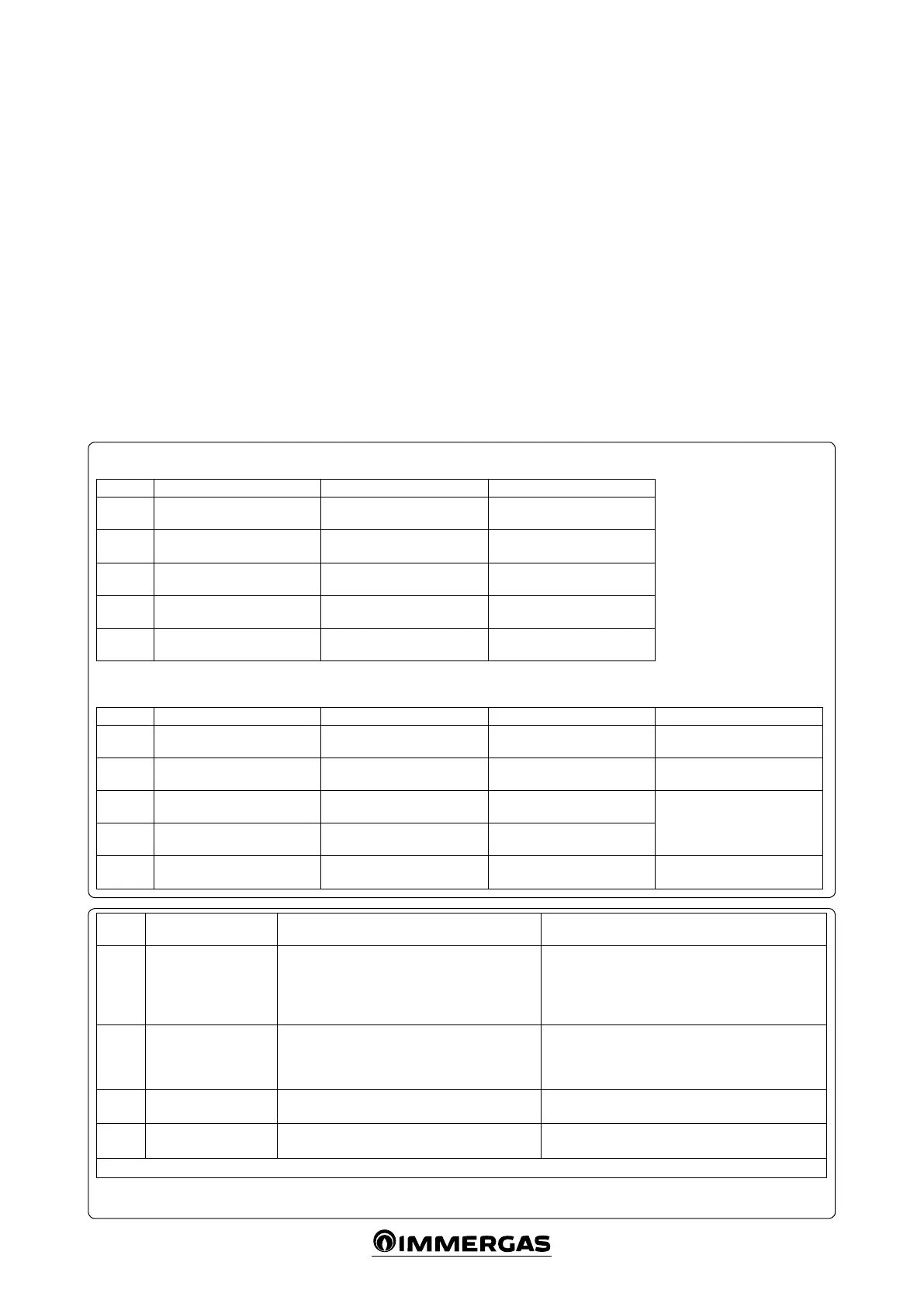
e system operating status is indicated by LEDs
(Ref. 10 Fig. 12 ) according to the relative tables
(Fig. 13).
FAULT AND ANOMALY SIGNALS.
e P.C.B. reports a fault by means of a code
shown on the remote control display, according
to the table below and the table in the boiler
instruction booklet. Depending on the settings
of the relevant parameters, it is possible to decide
on which remote control the fault is displayed
(Par. “Programming the P.C.B.”).
System with 1 high temperature zone and 1 low temperature zone.
LED O On Slow Flashing Fast Flashing
DL1
(Red)
No remote control communica-
tion in OT-S1
Remote control presence in
OT-S1
Zone 1 active request Open safety thermostat
DL2
(Red)
Operation with Room er-
mostat
Remote control presence in
OT-S2
Zone 2 active request /
DL3
(Red)
Mixing valve stopped Mixing valve opening /
Low temperature zone probe
anomaly
(simultaneous ashing)
DL4
(Red)
Mixing valve stopped Mixing valve closing /
DL5
(Green)
No communication with boiler
Communication with boiler in
progress
DHW request in progress /
System with high temperature zones
LED O On Slow Flashing
DL1
(Red)
No remote control communica-
tion in OT-S1
Remote control 1 presence Zone 1 active request
DL2
(Red)
Operation with TA2 Remote control 2 presence Zone 2 active request
DL3
(Red)
Operation with TA3 Remote control 3 presence Zone 3 active request
DL4
(Red)
Operation with TA4 Remote control 4 presence Zone 4 active request
DL5
(Green)
No communication with boiler
Communication with boiler in
progress
Boiler in domestic hot water
operating mode
Perform the electrical connection as required and
as shown in the following wiring diagrams (Par.
“Wiring diagrams”).
SYSTEM USE.
- DHW temperature setting. e domestic hot
water temperature is controlled by the “master”
remote control, i.e. the one connected to the
OT-S1 channel of the kit connected to the boil-
er. e settings made on the remaining remote
controls for domestic hot water are ignored.
- Flow temperature setting. The boiler flow
temperature for central heating can be ad-
justed on each remote control as required. Or
in the case of a system controlled from room
thermostats, the ow temperature is set on the
relative parameters (Par. “Programming the
P.C.B.”). e system takes into consideration
the highest temperature in order to meet all
the active requests.
Error
Code
Anomaly signalled Cause Boiler status / Solution
36
IMG Bus communica-
tion loss
Communication between the components is inter-
rupted due to a fault on the boiler, multi-zone kit
or IMG Bus.
Disconnect and reconnect the power to the boiler. If the
Remote Control is still not detected on re-starting, the
boiler will switch to local operating mode, i.e. using the
controls on the control panel. In this case, the boiler
will not meet the heating requests (1)
68
Communication
failure between remote
control and multi-zone
kit
Due to a fault, communication between remote
control and multi-zone kit is interrupted.
Check the connection between the devices. In this case,
the boiler will meet the heating requests according to
the settings of the “Emergency Function” parameters
(1)
46
System protection
thermostat fault
e board detects a fault on the system protection
thermostat (optional).
e requests of the mixed zone (low temperature) are
not met (1)
55
Low temperature zone
probe anomaly
e board detects a fault on the low temperature
probe (optional).
e requests of the mixed zone (low temperature) are
not met (1)
(1) If the block or anomaly persists, contact an authorised company (e.g. Immergas Technical Aer-Sales Service).
ELECTRICAL CONNECTION.
e kit has an IP20 protection rating; electrical
safety of the appliance is achieved only when it
is properly connected to an ecient earthing
system, as specied by current safety standards.
Attention: the manufacturer declines any re-
sponsibility for damage or physical injury caused
by failure to connect the kit to an ecient earth
system or failure to comply with IEC reference
standards.
Important: it is mandatory to prepare two elec-
trical connection lines in order to separate the
electrical power supply from all other low-voltage
connections, according to the standards in force
regarding electrical systems.
e electrical connection between the devices
must be made using cables with a minimum
section of 0.50 mm
2
and with a maximum section
of 2.5 mm
2
; the length of these connections must
not exceed 15 metres.
14