15
In the case of using 2 multi-zone cascade boards,
you have to program the individual board BE-
FORE making all the connections, as the OT-S1
channel may already be used to connect the
boards themselves.
PROGRAMMING THE P.C.B.
All functions can only be set from the remote
“master” command, i.e. connected to the OT-S1
channel of the board.
to access these functions, the 4-digit code must
be entered (code: 9988).
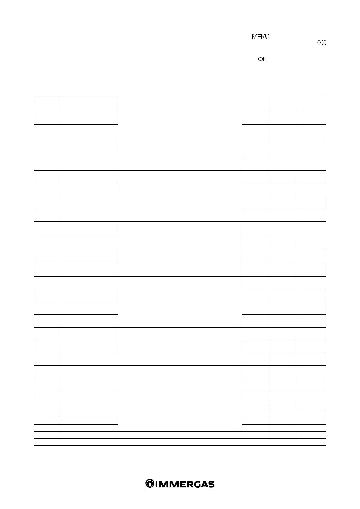
Parameter
Number
Description of the Parameter
Values
Field
Default
Customised
value
TSP001 Zone 1 emergency function
With the function active, in the event that communication
between the multi-zone kit and the remote control fails, a
room heating request is activated in the zone in question. is
request is met at a xed and preset temperature, it is possible
to set the temperature through TSP009, TSP010, TSP011,
TSP012.
e function is disabled as soon as communication with the
remote control is restored.
0÷1 * 0
TSP002 Zone 2 emergency function 0÷1 * 0
TSP003 Zone 3 emergency function 0÷1 * 0
TSP004 Zone 4 emergency function 0÷1 * 0
TSP005
Fault display on zone 1
remote control
By enabling this parameter, it is possible to display the system
faults on the remote control.
0÷1 * 1
TSP006
Fault display on zone 2
remote control
0÷1 * 0
TSP007
Fault display on zone 3
remote control
0÷1 * 0
TSP008
Fault display on zone 4
remote control
0÷1 * 0
TSP009 Zone 1 emergency set-point
System with 4 high temperature zones: it denes the ow tem-
perature for the “emergency” function on the 4 available zones.
System with 1 high temperature zone and 1 low temperature
zone: TSP009 and TSP010 dene the ow temperature for
the “emergency” function on the 2 available zones; parameter
TSP011 denes the temperature correction on the mixed zone
and parameter TSP012 denes the maximum temperature on
the mixed zone.
20÷90°C 60°C
TSP010 Zone 2 emergency set-point 20÷90°C 60°C
TSP011
Zone 3 emergency set-point
/ mixing valve IN-OUT ΔT
20÷90°C
/ 5÷30°C
60°C / 10°C
TSP012
Zone 4 emergency set-point
/ mixing valve max out
20÷90°C
/ 20÷70°C
60°C / 50°C
TSP013
Zone 1 post-circulation
timer
At the end of each room heating request, post-circulation is
performed on the same zone with set duration.
1÷240 min. 1min .
TSP014
Zone 2 post-circulation
timer
1÷240 min . 1min .
TSP015
Zone 3 post-circulation
timer
1÷240 min . 1min .
TSP016
Zone 4 post-circulation
timer
1÷240 min . 1min .
TSP017
Zone 2 room thermostat
set-point
If zones 2, 3 and 4 are controlled by room thermostats, it is
possible to dene the system ow temperature on the respec-
tive parameters.
20÷90°C 60°C
TSP018
Zone 3 room thermostat
set-point
20÷90°C 60°C
TSP019
Zone 4 room thermostat
set-point
20÷90°C 60°C
TSP020
Adjustment K with zone 2
room thermostat
If zones 2, 3 and 4 are controlled by room thermostats, it is
possible to dene the “K” correction for the ow temperature
associated with the external probe (optional).
0÷90 60
TSP021
Adjustment K with zone 3
room thermostat
0÷90 60
TSP022
Adjustment K with zone 4
room thermostat
0÷90 60
TSP023 Zone 1 heat request delay
With thermal system controlled by thermostatic valves, it
denes the valve activation time.
0÷255 sec. 0
TSP024 Zone 2 heat request delay 0÷255 sec. 0
TSP025 Zone 3 heat request delay 0÷255 sec. 0
TSP026 Zone 4 heat request delay 0÷255 sec. 0
TSP027 Mixing valve closing time It denes the closing time for the mixing valve. 0÷255 sec. 180
* (0:disabled, 1:enabled)
Press the
button and scroll the options
present until “CODE” appears, press the
button and enter the code by selecting the digits
using the + / - buttons and conrming them by
pressing the button.
Aer which it is possible to display and modify
the following functions.