Selecting Functions 5-19
5
•
Select the monitoring item to be output at the
FM terminal.
F31
Target of Definition of 100% of
monitoring monitoring amount
0 Output frequency 1 Maximum output
(before slip frequency
compensation)
1 Output frequency 2 Maximum output
(after slip frequency
compensation)
2 Output current 2 times rated inverter
output current
3 Output voltage 250V (200V class) ,
500V (400V class)
4 Output torque 2 times rated motor
torque
5 Load factor 2 times rated motor
load
6 Input power 2 times rated inverter
output
7 PID feedback value 100% feedback value
8 DC link circuit voltage 500V (200V class)
1000V (400V class)
Setting
FMP (Pulse rate)
FMP (Voltage adjust)
FMP (Function)
The output frequency, output current and other
monitor data can be output at the FM terminal in
pulse voltages. The average voltage can be
connected to an analog meter.
To select the pulse output and connect a digital
counter or the like, set the F33 pulse rate to a
desired value and set the F34 voltage to 0%.
To select the average voltage and connect an
analog meter, set the F34 voltage to determine
the average voltage; the F33 pulse rate is fixed
at 2670 [p/s].
Note) To use the FM terminal for the pulse
output, set F29 to "1" and set SW1 on
the control board to the FMP side.
•
Set the pulse frequency corresponding to 100
[%] of the monitoring amount of the
monitoring item selected by F35 in a range
from 300 to 6000 [p/s].
Setting range: 300 to 6000 [p/s]
F33
F35
F34
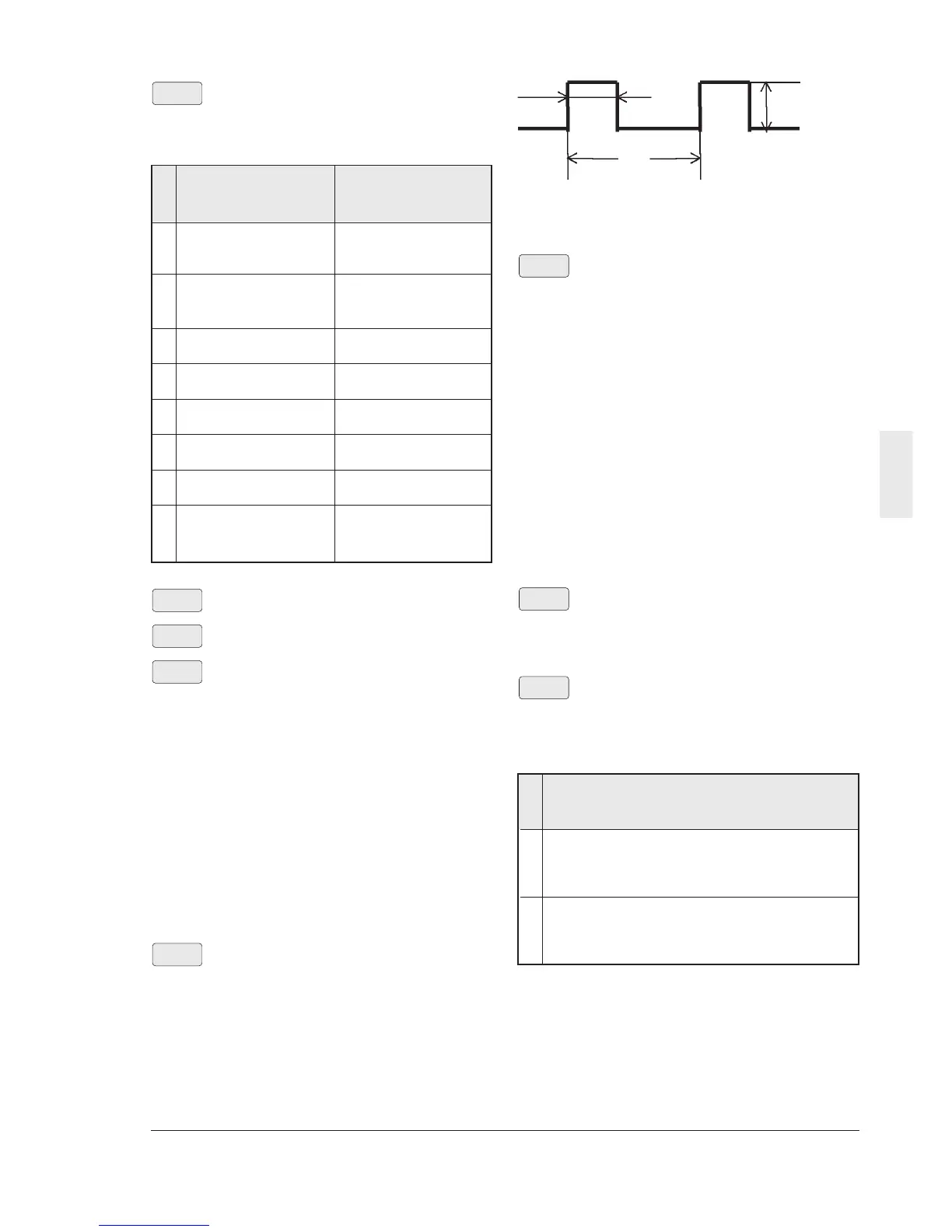
F33
T1
Approx 15.6 [V]
T
Pulse period
Pulse period [p/s] = 1/T
Duty [%] = T1/T X 100
Average voltage [V] = 15.6 X T1/T
•
Set the average voltage of the pulse output at
the FM terminal.
Setting range: 0 to 200 [%]
However, if "0" is set, the pulse frequency
varies according to the monitoring amount of
the monitoring item selected at F35 (with the
maximum value being the F33 setting). If a
value between 1 and 200 is set, the pulse
frequency is fixed at 2670 [p/s]. The average
voltage corresponding to 100 [%] of the
monitoring amount of the monitoring item
selected at F35 is adjusted in a range
between 1 and 200 [%] (in an increment of 1
[%]). (The duty of the pulse changes.)
Note : FMP has approx. 0.2V offset voltage
even
if FMP outputs zero value.
•
Select the monitoring item to be output at the
FM terminal. The options to be selected are
the same as F31.
30Ry operation mode
•
Select whether the alarm output relay (30Ry)
of the inverter is activated (excited) during
normal operation or during a trip.
F36
F35
F34
Description of operation
0 During normal operation 30A - 30C: OPEN
30B - 30C: CLOSE
Upon a trip condition 30A - 30C: CLOSE
30B - 30C: OPEN
1 During normal operation 30A - 30C: CLOSE
30B - 30C: OPEN
Upon a trip condition 30A - 30C: OPEN
30B - 30C: CLOSE
Setting
Note) Because the contact between 30A and
30C is on after the inverter is turned on (after
about 1 second since the power is turned on)
when the setting is "1", care must be taken to
the sequence design.