Selecting Functions 5-11
5
Operation method
•
The operation input method is set. (Note:
This function can be changed only when the
FWD and REV terminals are open.)
0: The motor starts or stops upon keypad
operation ( or key).
F02
5-2 Detail Description of Each
Function
F: Fundamental functions
Data protection
•
The setting data can be protected against
inadvertent operation at the keypad panel.
0: Data change enabled
1: Data protected
[Setting method]
0→1: Press the + keys simultaneously.
1→0: Press the + keys simultaneously.
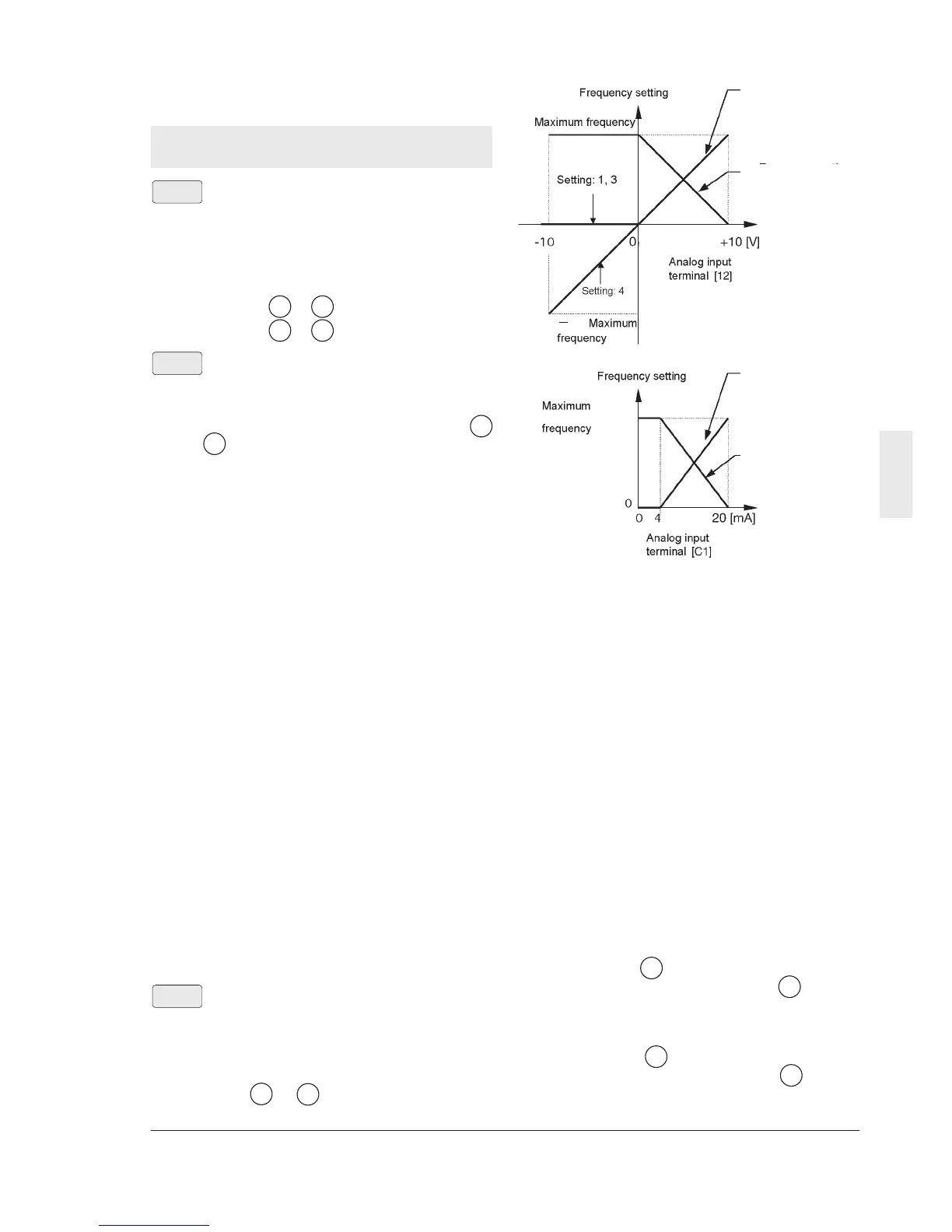
Frequency command 1
•
The frequency setting method can be
selected.
0: The frequency is set by the operation of I
and keys.
1: The frequency is set by the voltage input
(at terminal 12) (0 to +10 Vdc).
2: The frequency is set by the current input (at
terminal C1) (4 to 20 mAdc).
3: The frequency is set by the voltage input
and current input (terminal 12 and terminal
C1) ((-10 to +10 Vdc) + (4 to 20 mAdc)).
Inputs at terminals 12 and C1 are added to
determine the frequency.
4: The frequency is set by the voltage input with
polarity (at terminal 12) (-10 to +10 Vdc).
In the case of input with polarity, operation
at a direction opposite to the operation
command is possible.
5: The frequency is set by voltage input
inverse mode operation (at terminal 12)
(+10 to 0 Vdc).
6: The frequency is set by current input
inverse mode operation (at terminal C1) (20
to 4 mAdc).
7: UP/DOWN control mode 1
The frequency is set by terminal UP,
terminal DOWN. (initial value = 0)
8: UP/DOWN control mode 2
The frequency is set by terminal UP,
terminal DOWN (initial value = last value
during previous operation).
Refer to the description of the E01 to E05
functions for details.
F01
F00
STOP
V
STOP
V
V
V
RUN
STOP
Description of forward and reverse operation
The direction of rotation is determined by
the FWD and REV terminals on the control
terminal block as follows.
FWD-P24 short-circuited:Forward rotation
REV-P24 short-circuited: Reverse rotation
The motor does not start if both the FWD
and REV terminals are connected with the
P24 terminal or both of them are open.
1: External signal (digital input)
The motor starts or stops upon the state of
the FWD and REV terminals on the control
terminal block.
FWD-P24 short-circuited:forward rotation
REV-P24 short-circuited: reverse rotation
The motor does not start if both the FWD
and REV terminals are connected with the
P24 terminal or both of them are open.
2: Keypad operation (forward rotation only)
The motor runs in the forward direction
when the key is pressed and it
decelerates to stop when the key is
pressed.
3: Keypad operation (reverse rotation only)
The motor runs in the reverse direction
when the key is pressed and it
decelerates to stop when the key is
pressed.
RUN
STOP
RUN
STOP
Normal mode operaton
(setting: 1.3,4
Normal mode operaton
(setting: 2
Inverse mode operaton
(setting: 5
Inverse mode operaton
(setting: 5