Combination of input Selected frequency
signals
3210
[SS8] [SS4] [SS2] [SS1]
off off off off Selected by F01 or C30
off off off on C05 Multistep frequency 1
off off on off C06 Multistep frequency 2
off off on on C07 Multistep frequency 3
off on off off C08 Multistep frequency 4
off on off on C09 Multistep frequency 5
off on on off C10 Multistep frequency 6
off on on on C11 Multistep frequency 7
on off off off C12 Multistep frequency 8
on off off on C13 Multistep frequency 9
on off on off C14 Multistep frequency 10
on off on on C15 Multistep frequency 11
on on off off C16 Multistep frequency 12
on on off on C17 Multistep frequency 13
on on on off C18 Multistep frequency 14
on on on on C19 Multistep frequency 15
Selecting Functions 5-21
5
E:Extension Terminal Functions
X1 terminal function
X2 terminal function
X3 terminal function
X4 terminal function
X5 terminal function
•
The function of each digital input terminal X1
to X5 can be set arbitrarily using a code.
E05
E04
E03
E02
E01
Setting Function
0,1,2,3 Multistep frequency selection
(1 to 15 steps)
4 Acceleration/deceleration selection
(1 step)
5 Self holding selection [HLD]
6 Coast-to-stop command [BX]
7 Error reset [RST]
8 External alarm [THR]
9 Frequency setting 2 / frequency setting
1 [Hz2 / Hz1]
10 Motor 2 / motor 1 [M2 / M1]
11 DC brake command [DCBRK]
12 Torque limit 2 / torque limit 1 [TL2 / TL1]
13 UP command [UP]
14 DOWN command [DOWN]
15 Write enable for keypad (data change
allowed) [WE-KP]
16 PID control cancel [Hz / PID]
17 Forward/reverse operation switch
(terminal 12 and terminal C1) [IVS]
18 Link operation selection
(RS485 standard, BUS Option) [LE]
Note) The data numbers not assigned to E01
through E05 are considered to be
inactive.
Multistep frequency
Frequencies set to function codes C05 through
C19 can be selected according to external
digital input signal switching. Set data 0 to 3 to
the desired digital input terminals and
combination of input signals determines the
selected frequency.
Multistep frequency selection
Acceleration/deceleration time selection
Acceleration/deceleration time set to function
codes E10 and E11 can be selected according
to external digital input signal switching.
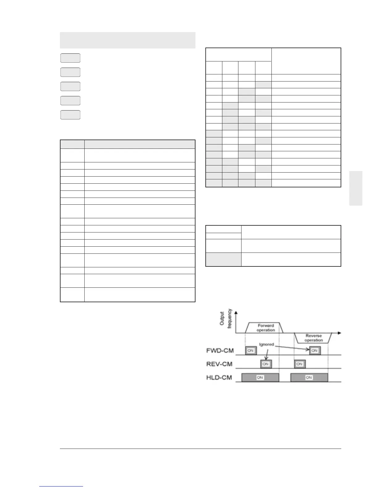
3-wire operation stop command [HLD]
Used for three-wire operation. When HLD-P24
is ON, the FWD or REV signal is maintained,
and when it is OFF, the signal is reset.
Note : The inverter operates while FWD-P24 or
REV-P24 is ON even if HLD-P24 is OFF.
An external interlock sequence ,which
makes FWD-P24 and REV-P24 OFF
when HLD-P24 is OFF, is required.
Input signal Selected
4[RT1] acceleration/deceleration time
off F07 Acceleration time 1
F08 Deceleration time 1
on E10 Acceleration time 2
E11 Deceleration time 2