Specifications 9-12
9
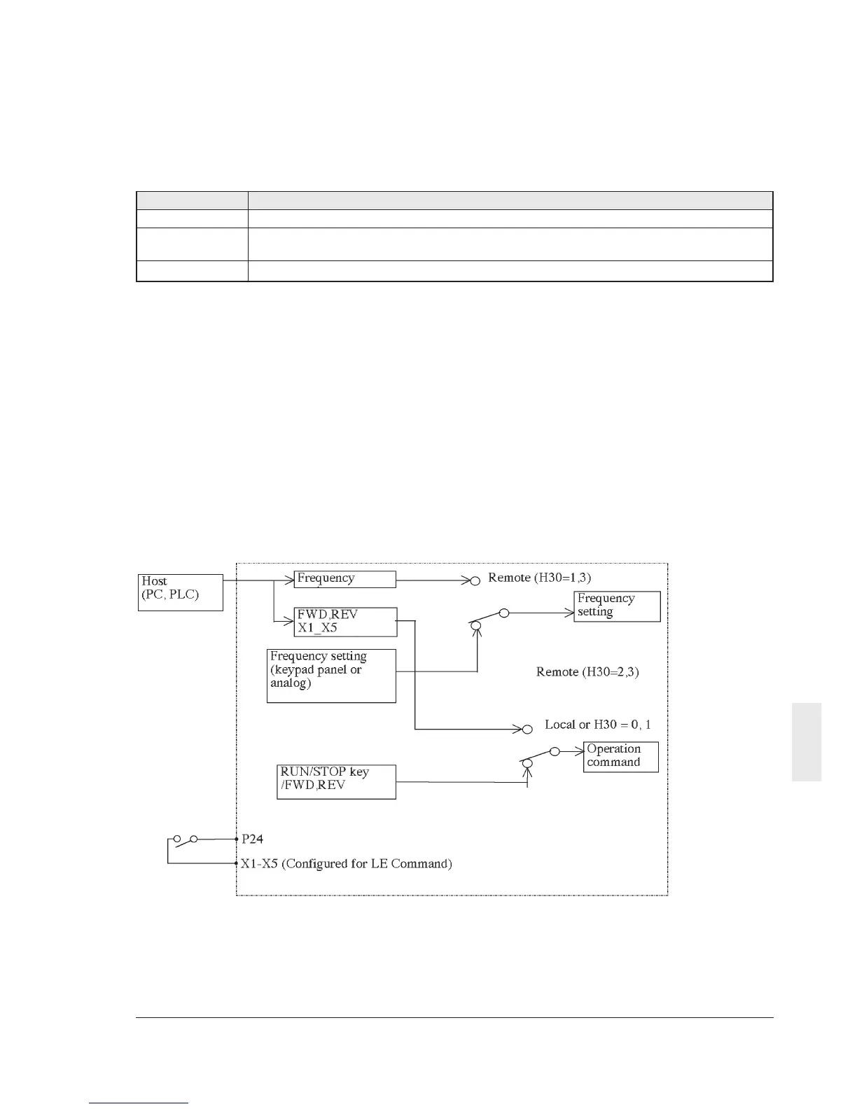
Fig. 9-4-3 Command switching block diagram
When X1 through X5 terminals are assigned
with BX, THR and RST functions, the BX, THR
and RST functions are activated even in the
remote mode according to the inputs to the
terminals. RS485 can not make THR ON/OFF.
9-4-1 Connector and Communication
Cable
Use marketed products for the connector, the
communication cable and branch adapter.
Table 9-4-2 shows the specification of each of
them.
Table 9-4-2 Connector and cable specification
9-4-2 Recommended RS-232C/RS485
Converter
For communications with PCs having an
RS232C terminal, the following isolation type
converter is recommended.
Model : IDACS-1520
Manufacture : IMO Precision Controls Ltd
9-4-3 Remote/local changeover
Operation between frequency setting and operation
commands sent via serial communication, and
according to the frequency setting and
Item Specification
Connector RJ45 connector
Cable Cable complying with EIA568 (for 10BASE-T Straight connection)
(Max. wiring length: 500m)
Branch adapter MS8-BA-JJJ (SK KOHKI CO., LTD or equivalent.)
operation commands set in the inverter main
body, can be switched over.
The frequency setting and operation command
selection is made as follows, using function H30
and remote/local switching.
The function of any of the X1 through X5
terminals of the inverter main body is changed
to be the LE terminal which is used for
remote/local switching. Any of the functions E01
through E05 is used to change the function of
X1 to X5 terminal. If X1 through X5 terminals are
not assigned to the LE terminal, it is always in
the remote mode.