Installation and Connection 5-25
5
OL function signal (Mode select)
•
The OL function signal includes two
variations: "overload forecast by means of the
function of the electronic thermal overload
relay" and "overload forecast by means of
output current".
Setting: 0 Electronic thermal overload relay
1 Output current
E33
Setting Function Outline
0 Electronic Overload forecast using the
thermal characteristics of the
overload electronic thermal overload
relay relay which show inverse time
limit characteristics against
the output current.
The operation selection of the
inverse time limit
characteristics and the
thermal time constant are the
same characteristics as those
of the electronic thermal
overload relay (F10, F12) for
motor protection. To use for
the forecast, set an earlier
output than the electronic
thermal overload relay for
motor protection.
1 Output When the output current
current exceeds the set current for a
period longer than the set
time, an overload forecast is
issued.
OL function signal (Level)
Determine the level of the electronic thermal
overload relay or output current.
Setting range:
Rated inverter output current x (20 to 200%)
The operation cancellation level is 90% of the
set value.
OL function signal (Timer)
•
When E33 "OL function signal (Mode select)"
is set at "1" (output current), set the time
taken until the forecast is issued.
Setting range: 0.1 to 60.0 s
E35
E34
Display coefficient A
Display coefficient B
•
Use these functions as conversion
coefficients for determining the display value
(process amount) of the load speed, line
speed and target value and feedback amount
of the PID adjuster.
Setting range
Display coefficient A: 0.00 to 200.0
Display coefficient B: 0.00 to 200.0
•
Load speed and line speed
Use E40 "Display coefficient A".
(Displayed value) = (Output frequency) x
(0.01 to 200.0)
The effective value of the display data is 0.01
to 200.0. Therefore the display is limited by
the minimum value of 0.01 and the maximum
value of 200.0 even if the value exceeds the
range.
•
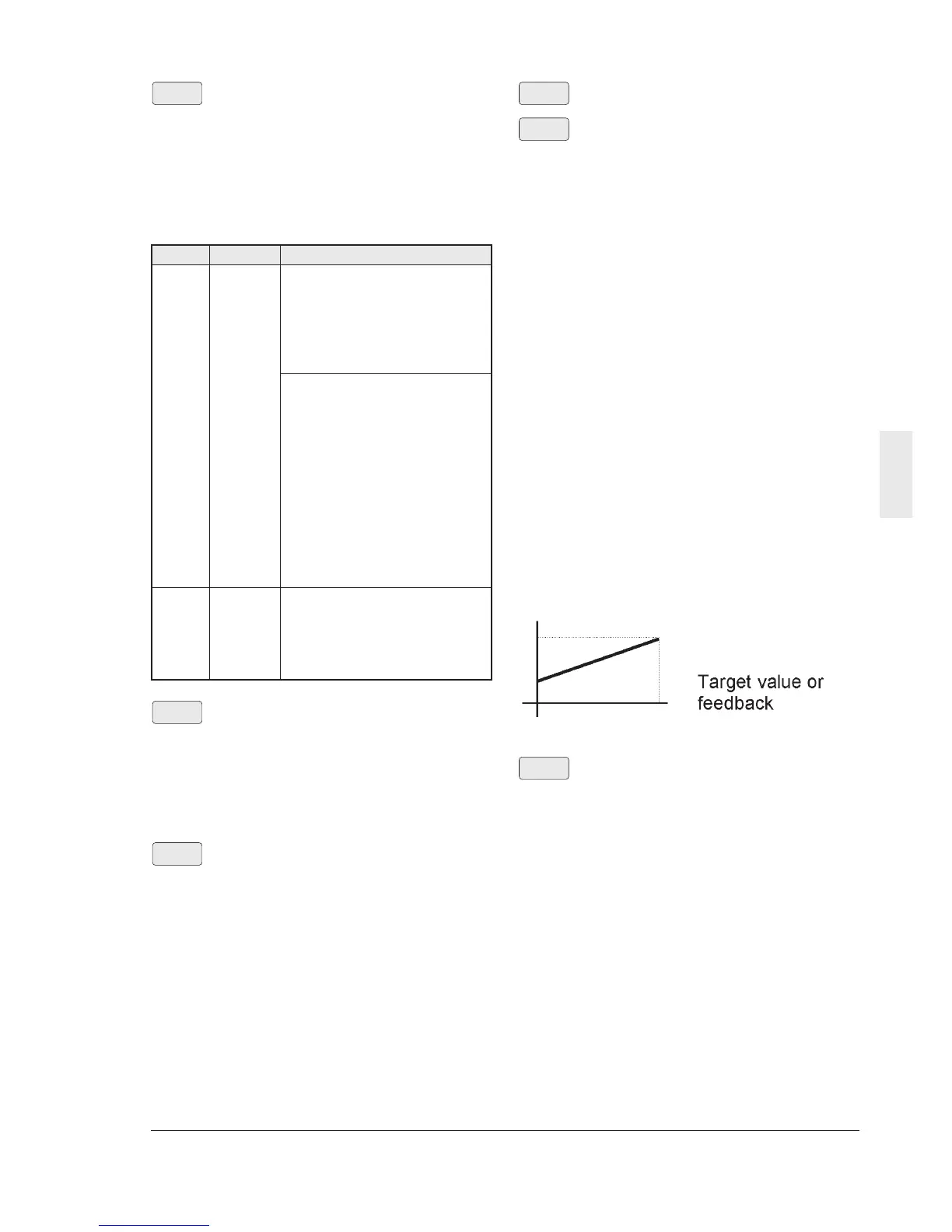
Target value and feedback amount of PID
adjuster
Set the maximum value of the display data at
E40 "Display coefficient A" and set the
minimum value at E41 "Display coefficient B".
Display value = (Target value or feedback
amount) x (Display coefficient A - B) + B
E41
E40
LED display filter
The data of "LED monitor" includes data for
which display of the changing moment is not
necessary. This type of data can be provided
with a filter for flicker prevention.
Setting range: 0.0 to 5.0 s
•
The target display items are the output
current and output voltage.
E42
A
B
0%
100%