Specifications 9-2
9
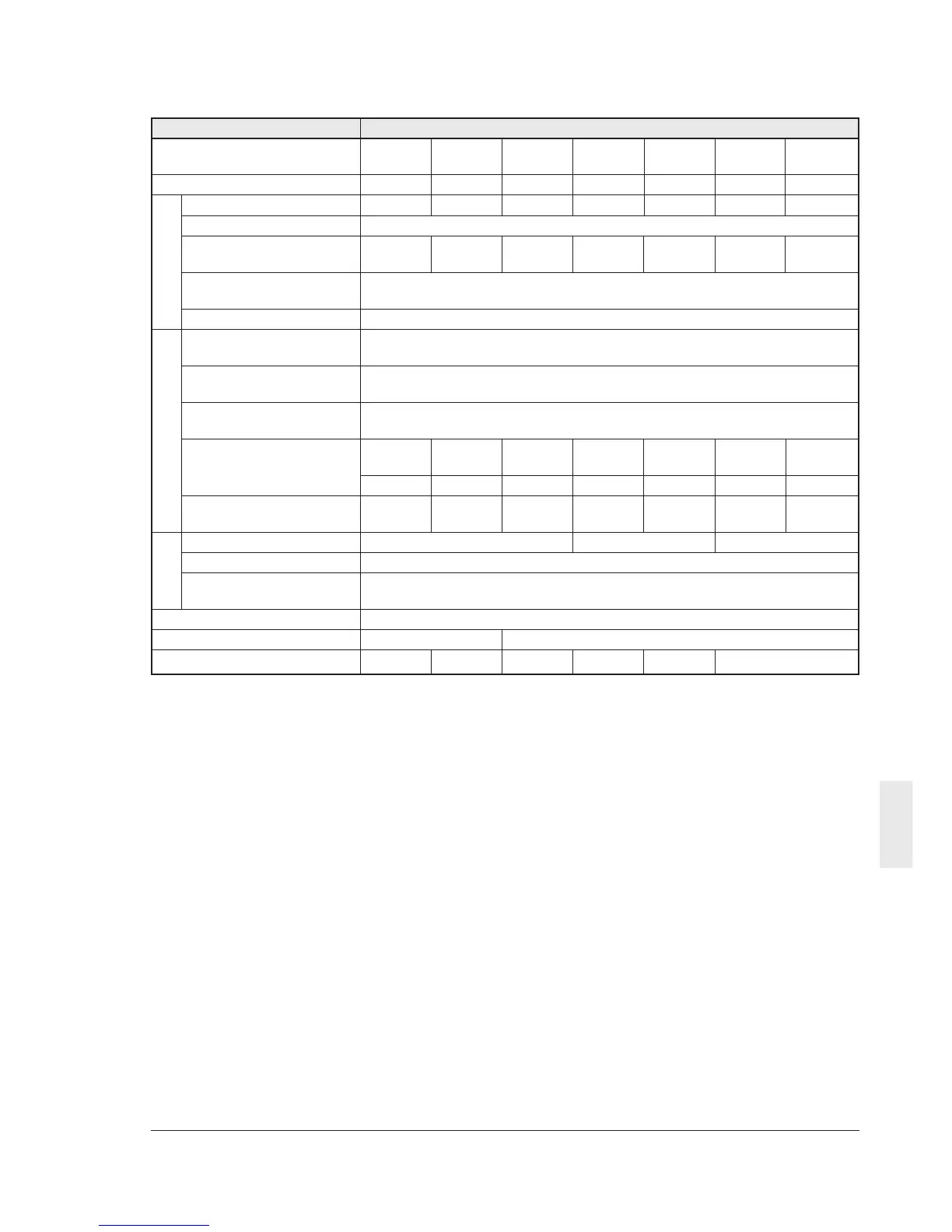
Item Detail specifications
Inverter type
VXSM 40-3 75-3 150-3 220-3 400-3 550-3 750-3
Nominal applied motor *
1
[kW]
0.4 0.75 1.5 2.2 4.0 5.5 7.5
Rated capacity *
2
[kVA] 1.1 1.8 2.6 3.9 6.5 9.3 13
Rated voltage *
3
[V]
Three-phase 380,400,415V/50Hz, 380,400,440,460V/60Hz (with AVR function)
Rated current *
4
[A] 1.5 2.5 3.7 5.5 9.0 13 18
(1.4) (2.1) (3.7) (5.3) (8.7) (12) (16)
Overload capability 150% of rated output current for 1 min.
200% of rated output current for 0.5 s
Rated frequency [Hz] 50, 60Hz
Phases, Voltage, Three-phase 380 to 480 V / 50 to 60 Hz *
11
Frequency
Voltage/frequency Voltage : +10 to -15% Voltage unbalance 2% or less*
10
fluctuation Frequency : +5 to -5%
Momentary voltage Operation continues at 300V or higher voltage. When the input voltage
dip capability *
5
drops below 300V from the rated voltage, operation continues for 15 ms.
Rated current [A] 0.82 1.5 2.9 4.2 7.1 10.0 13.5
(With DCR)
(Without DCR) *
9
1.8 3.5 6.2 9.2 14.9 21.5 27.9
Required power supply 0.6 1.1 2.1 3.0 5.0 7.0 9.4
capacity *
6
[kVA]
Braking torque *
7
[%] 70 40 20
Braking torque *
8
[%] 150
DC braking Starting frequency: 0.0 to 60 Hz, braking current (0 to 100% in 1%
increment), braking time (0.0 to 30.0 s)
Enclosure (IEC60529) IP20
Cooling method Natural cooling Fan cooling
Mass [kg] 1.1 1.2 1.3 1.4 1.9 4.5
Output ratingsInput ratings
Braking
(2) Three-phase 400V input
*1 The applicable standard motor indicates a 4
pole machine.
*2 The rated capacity indicates the case for
415V output voltage.
*3 Voltages larger than the source voltage
cannot be output.
*4 Amperage values in brackets () are
applicable to operation with 4 kHz or higher
carrier frequencies (F26 = 4 or more) or
ambient temperatures exceeding 40 degree C.
*5 Tests at standard load condition (85% load)
*6 Indicates the value when using a DC reactor
(DCR).
*7 Indicates the average braking torque for
decelerating and stopping a discrete motor
from 60 Hz. (Varies according to the
efficiency of the motor.)
*8 Indicates the value with an external braking
resistor (option).
*9 Calculated on assumption that the inverter is
connected to 500kVA power supply.
*10 Refer to IEC61800-3 5.2.3.
*11 Safe separation for control interface of this
inverter is provided when this inverter is
installed in overvoltage category II. Basic
insulation for control interface of this inverter
is provided when this inverter is installed in
overvoltage category III.