39
skcolCruoFehT
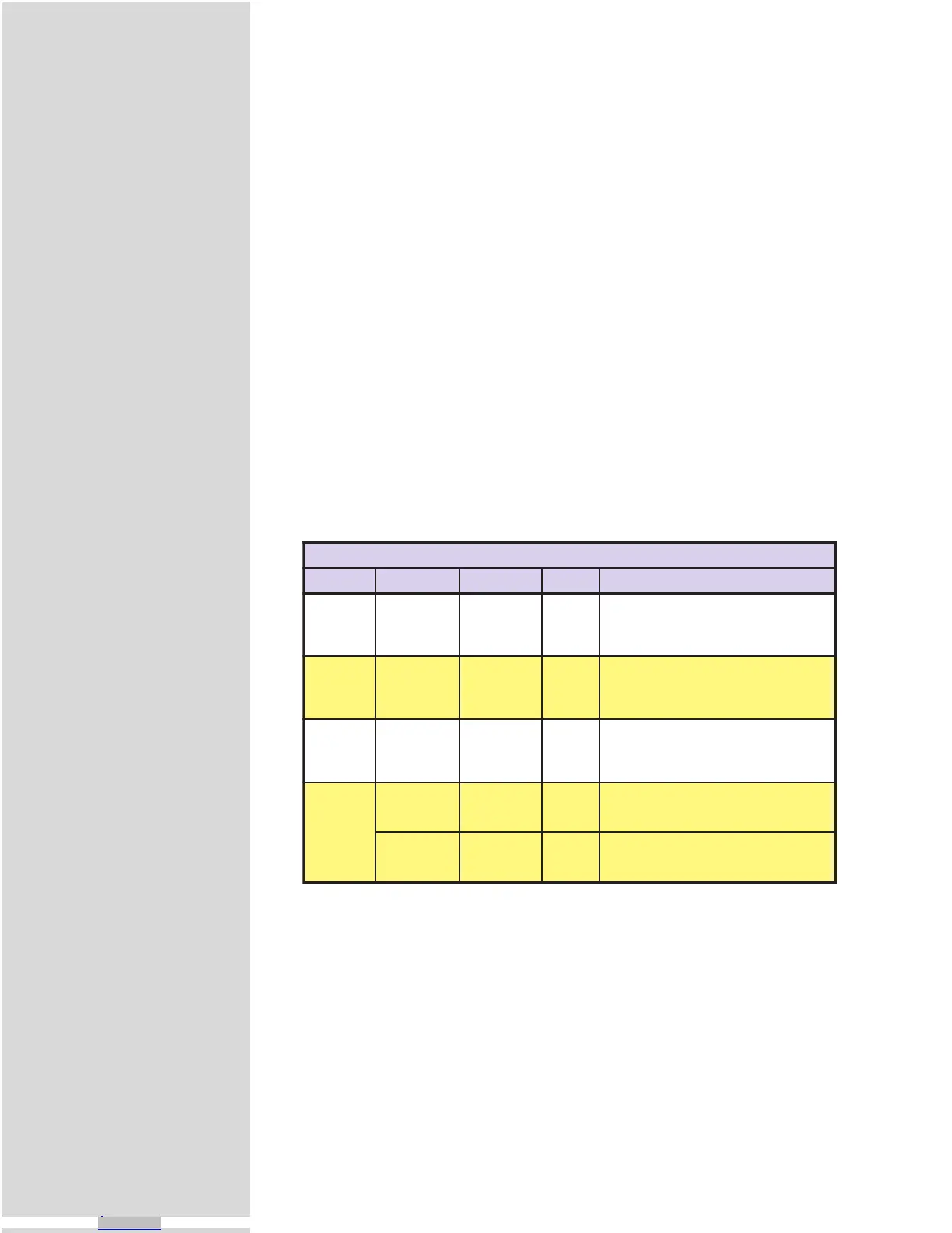
#kcolC riaPeniLO/I noitisoPtolS retnuoC noitcnuF
121&11enoN1RTC
.kcolcnoitomdetarenegyllanretnisikcolcsihT
otlortnoclanoitceriddnakcolcpetssedivorptI
elbaliavatonsikcolcsihT.noitcesrevirdeht
.rotcennoclanretxeynano
2 41&31 2tolS 2RTC
yB.tuptuorotupninasaderugifnocebyaM
.tupnierutardauqasaderugifnocsisihttluafed
kcolcyradnocesasaderugifnocebnactI
.1KLCotderaegyllacinortceletuptuo
361&513tolS3RTC
yB.tuptuorotupninasaderugifnocebyaM
.tupnierutardauqasaderugifnocsisihttluafed
tuptuokcolcyraitretasaderugifnocebnactI
.1KLCotderaegyllacinortcele
4
71 2tolS enoN
narotupnideepshgihasaderugifnocebyaM
ecnereferzHM1asitituptuonasA.tuptuo
.kcolc
81 3tolS enoN
rotupnideepshgihasaderugifnocebyaM
ecnereferzHM01asitituptuonasA.tuptuo
.kcolc
Table 9.5: The Four Clocks and Their Default Line Placement
1] Remove screws (A).
2] Remove panel from slot to be used (either Slot #2 or Slot #3).
3] Insert High-Speed Differential I/O Module into Slot 2 (C) or
Slot 3 (D).
4] Press firmly until expansion board is securely seated and locked
into place by retaining clips (F).
5] Reassemble MicroLYNX case in accordance with Figure 9.1.
6] Affix labels as shown. Use a highlighter or marker pen to
highlight slot(s) used.
The Four Clocks Explained
The MicroLYNX has four clock pairs that are used by the high-speed I/O. One of
these, clock pair 11 and 12, is fixed as an output and is used internally to provide
step clock and direction pulses to the driver section of the MicroLYNX. The step
clock output increments CTR1 (Counter 1). The user has no physical access to this
clock, however, CTR1 may be read from or written to by software instructions in
either program or immediate mode. The following table explains the clocks, as
well as their default I/O line pair placement:
Clock Types Defined
There are three basic types of clocks that may be configured for the MicroLYNX,
they are:
1] Quadrature
2] Step/Direction
3] Up/Down
These clock functions are illustrated in figure 9.5.
Downloaded from Arrow.com.Downloaded from Arrow.com.Downloaded from Arrow.com.Downloaded from Arrow.com.Downloaded from Arrow.com.Downloaded from Arrow.com.Downloaded from Arrow.com.Downloaded from Arrow.com.Downloaded from Arrow.com.Downloaded from Arrow.com.Downloaded from Arrow.com.Downloaded from Arrow.com.Downloaded from Arrow.com.Downloaded from Arrow.com.Downloaded from Arrow.com.Downloaded from Arrow.com.Downloaded from Arrow.com.Downloaded from Arrow.com.Downloaded from Arrow.com.Downloaded from Arrow.com.Downloaded from Arrow.com.Downloaded from Arrow.com.Downloaded from Arrow.com.Downloaded from Arrow.com.Downloaded from Arrow.com.Downloaded from Arrow.com.Downloaded from Arrow.com.Downloaded from Arrow.com.Downloaded from Arrow.com.Downloaded from Arrow.com.Downloaded from Arrow.com.Downloaded from Arrow.com.Downloaded from Arrow.com.Downloaded from Arrow.com.Downloaded from Arrow.com.Downloaded from Arrow.com.Downloaded from Arrow.com.Downloaded from Arrow.com.Downloaded from Arrow.com.Downloaded from Arrow.com.Downloaded from Arrow.com.