40
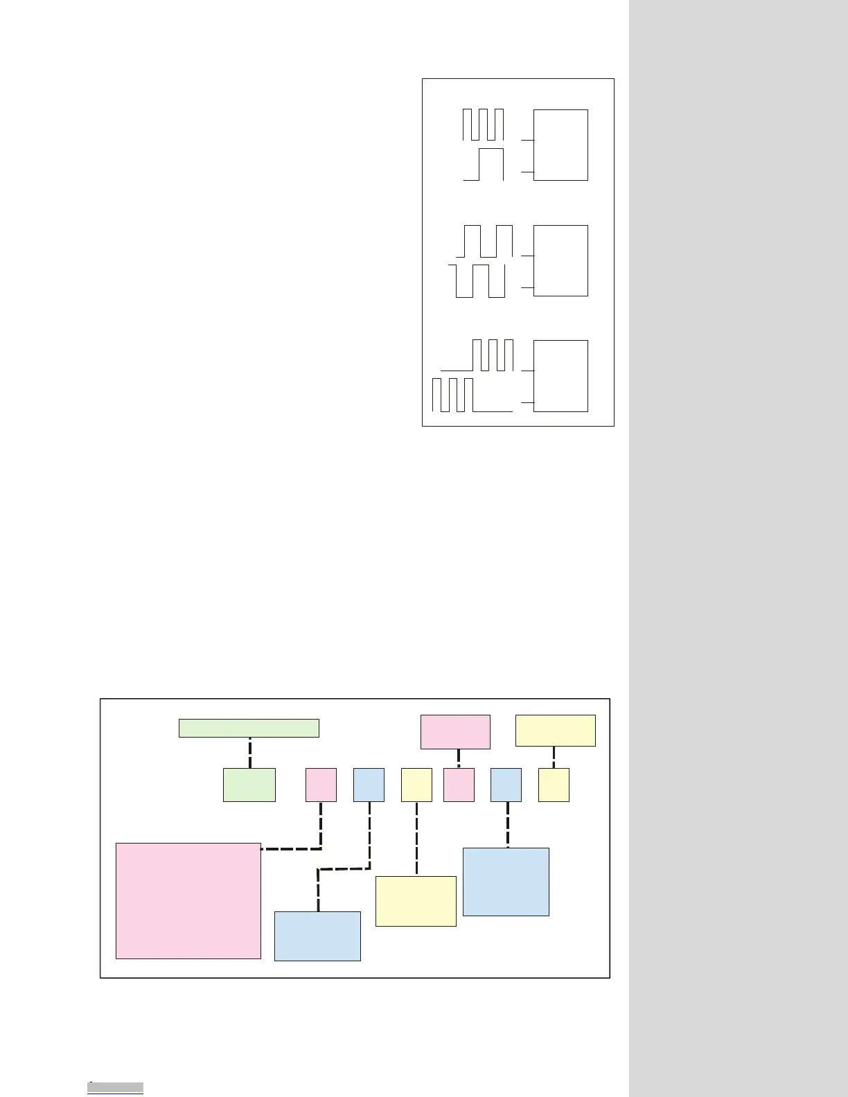
Quadrature
The quadrature clock function is the most
commonly used input clock function. This is
the default setting for each high-speed I/O
channel except 11 & 12. This clock function
will typically be used for closed loop control
(encoder feedback) or for following applica-
tions
Step/Direction
The step/direction clock funtion would typi-
cally be used in an application where a second-
ary or tertiary clock output is required to
sequentially control an additional axis.
Up/Down
The up/down clock type would typically be
used as an output function where a secondary
axis is being driven by a stepper or servo drive
with dual-clock direction control circuitry.
Configuring the Differential I/O - The IOS Variable
The high-speed differential I/O is configured by means of the IOS variable, and
is used in the the same fashion in which the isolated I/O is configured. The main
difference lies in that there are three additional parameters which need to be set
in configuring the triggering, clock type and ratio mode setting.
It is important to note that the high-speed differential I/O lines may be used for
the same input or output functions as the isolated digital I/O where the higher
speed capabilities of the differential I/O is required. However, for purposes of
this example we will only illustrate the clock functions associated with the high-
Step Clock
Direction
Channel A
Channel B
CW
CCW
Step Clock/Direction
Quadrature
Up/Down
Figure 9.5: Clock Functions
Figure 9.6: IOS Variable Settings for the High-Speed Differential I/O
IOS = , , , , ,
XXXX X XXX
Enter the Channel # (13-18) here!
Enter I/O Line Type # Here
1 = Clock 1A
2 =
3 =
4 =
5 =
6 =
7 =
8 =
Clock 1B
Clock 2A
Clock 2B
Clock 3A
Clock 3B
Clock 4A
Clock 4B
Define Line or Group
As Input or O utput
0 = Input
1 = Output
Define the Clock Type
0 = Not A Clock
1 = Quadrature
2 = S tep/D irection
3 = Up/D own
Set the state
of the Line or Group
0 = Active Low
1 = Active High
Set the Ratio Mode
0 = No R atio
1 =R atio
Set the Triggering
0 = Level
1 = Edge
NOTE: The
Clock # s are
fixed to their
associated I/O
channel and
cannot be
changed! They
are entered for
sake of consistency
only!
Downloaded from Arrow.com.Downloaded from Arrow.com.Downloaded from Arrow.com.Downloaded from Arrow.com.Downloaded from Arrow.com.Downloaded from Arrow.com.Downloaded from Arrow.com.Downloaded from Arrow.com.Downloaded from Arrow.com.Downloaded from Arrow.com.Downloaded from Arrow.com.Downloaded from Arrow.com.Downloaded from Arrow.com.Downloaded from Arrow.com.Downloaded from Arrow.com.Downloaded from Arrow.com.Downloaded from Arrow.com.Downloaded from Arrow.com.Downloaded from Arrow.com.Downloaded from Arrow.com.Downloaded from Arrow.com.Downloaded from Arrow.com.Downloaded from Arrow.com.Downloaded from Arrow.com.Downloaded from Arrow.com.Downloaded from Arrow.com.Downloaded from Arrow.com.Downloaded from Arrow.com.Downloaded from Arrow.com.Downloaded from Arrow.com.Downloaded from Arrow.com.Downloaded from Arrow.com.Downloaded from Arrow.com.Downloaded from Arrow.com.Downloaded from Arrow.com.Downloaded from Arrow.com.Downloaded from Arrow.com.Downloaded from Arrow.com.Downloaded from Arrow.com.Downloaded from Arrow.com.Downloaded from Arrow.com.Downloaded from Arrow.com.