99904235 DRAWING
8
28
28
27
24
18
18
2
32
17
27
32
17
27
33
36
35
24
27
28
8
28
9
39
40
42
46
0.50"
0.50"
6" TYP
6" TYP
72"
72"
6.0"
6.5"
6.0"
6.5"
START WITH
RED SEGMENT
43(5)
44(5)
23,28
24,27
(2 PLCS)
25,27,32 (2 PLCS)
22,28
21,27
(2 PLCS)
16,19
(2 PLCS)
15,20,30
(3 PLCS)
45(2)
30(2)
26(2)
6
5
8
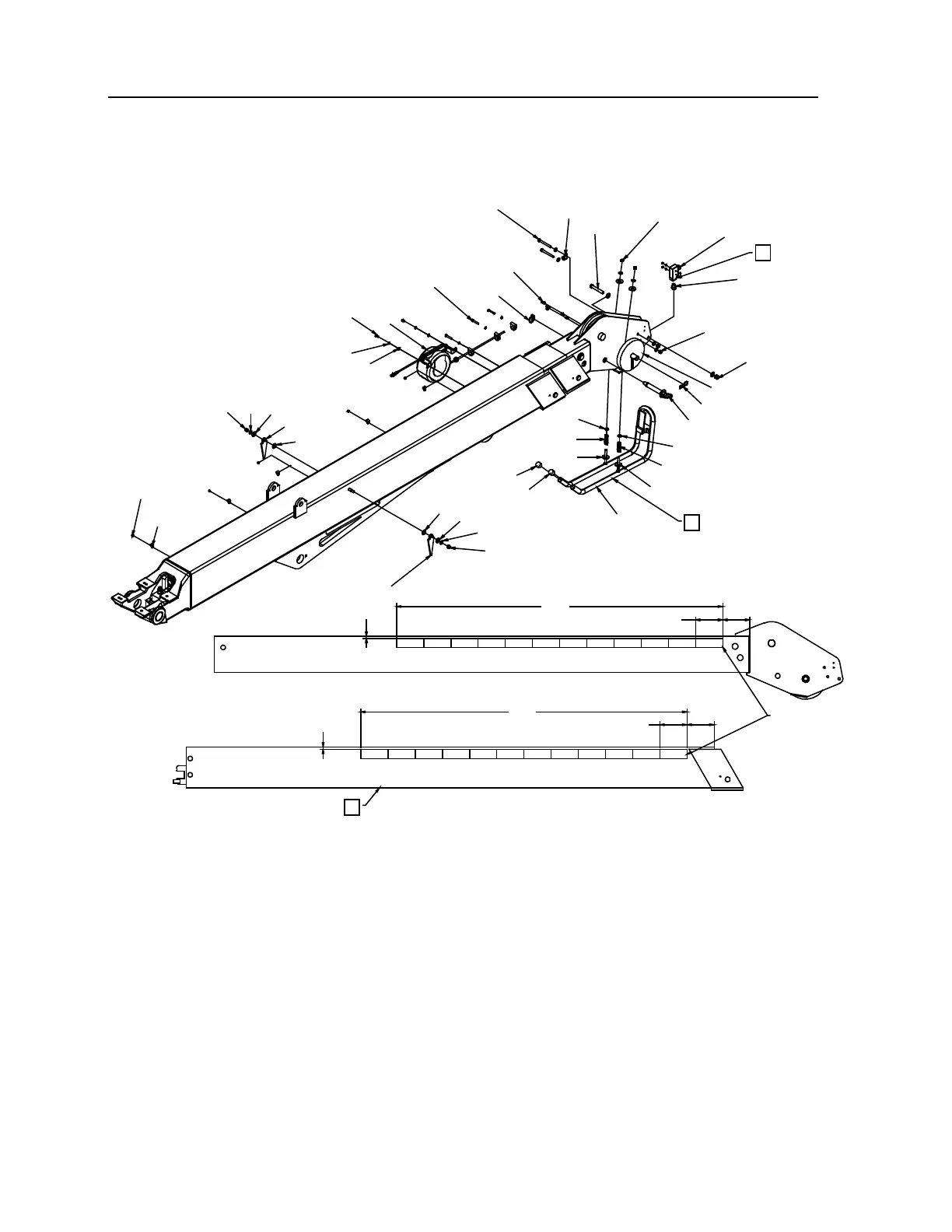
NOTES (IF PART OF DRAWING, SEE REFERENCE NUMBER IN BOX):
1 INSTALL ITEMS #41 AND #42 ON SNATCH BLOCK.
2 USE NEVER-SEEZ ON PIN.
3 TORQUE TO 280 FT-LB. USE BLUE THREAD LOCKER.
4 INSTALL EXTENSION CYLINDERS FIRST, RETAINERS NEXT, AND WEAR PADS LAST.
5 ADJUST TENSION TO ALLOW SWITCH TO FUNCTION.
6 MOUNTING HARDWARE INCLUDED WITH SWITCH. (USE O-RINGS, SCREWS, AND #6 NYLOCK HEX
NUTS.)
7 APPLY BOOM LENGTH INDICATOR TAPE ON BOTH SIDES OF BOOM AND EXTENSION. START WITH
RED SEGMENT.
8 SHOWS 1ST STAGE EXTENSION BOOM.
 Loading...


