In This Chapter
General Specifications.............................................................. 7
System Specifications .............................................................. 8
Geometric Configuration, 5525-6025-6625 ............................... 10
Capacity Chart, 5525 ................................................................ 11
Capacity Chart, 6025 ................................................................ 12
Capacity Chart, 6625 ................................................................ 13
Reduced Capacity Lift Charts ................................................... 14
Stability Confirmation Process .................................................. 15
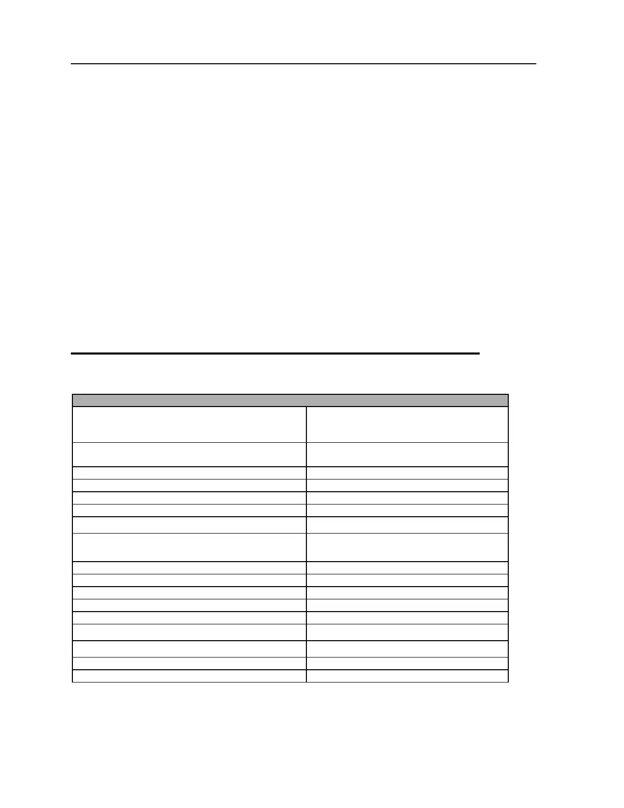
General Specifications
Model 5525 - 55,000 ft-lb (7.6 tm)
Model 6025 - 60,000 ft-lb (8.3 tm)
Model 6625 - 66,000 ft-lb (9.1 tm)
HORIZONTAL REACH (From centerline of
rotation)
78" & 78" (198.1 cm & 198.1 cm)
LIFTING HEIGHT (From base of crane)
STABILIZER SPAN (Required option)
Crane Side (From centerline of chassis)
Opposite Crane Side (From centerline of
chassis)
MOUNTING SPACE REQUIRED (Crane base)
20" x 21" (50.8 cm x 53.3 cm)
SYSTEM OPERATING PRESSURE
Horizontal from Centerline of Rotation
Vertical from Bottom of Crane Base
TIE-DOWN BOLT PATTERN (8 bolts)
14-3/4" x 14-3/4" (37.5 cm x 37.5 cm)
* Crane rating (ft-lb) is the rated load (lb) multiplied by the respective distance (ft) from centerline of
rotation with all extensions retracted and lower boom in horizontal position.
Specifications
 Loading...


