32
tina56e1-f (2015-09)
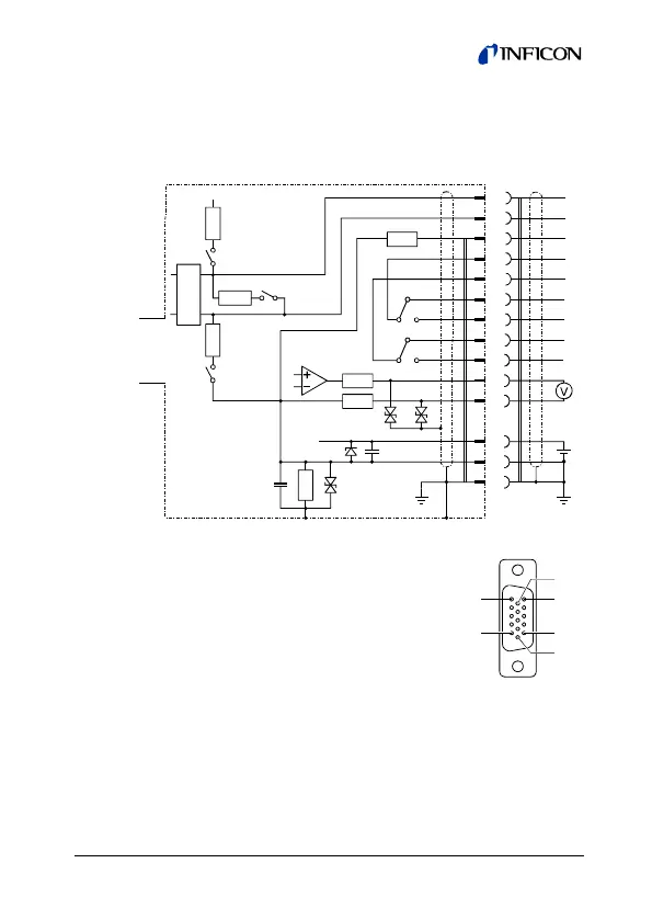
3.2.4 D-Sub HD, 15-pin, RS485 INF Connector
If no sensor cable is available, make one according to the
following diagram. Connect the sensor cable.
11
15
5
6
3
4
12
14
+
–
+
–
+24V
10
13
SP1
SP2
4.7
Ω
4.7Ω
10k
18V
8
2
1
RS-485
10Ω
470
Ω
120Ω
2 Termination
3
Fail safe
bias
470
Ω
+5V
1 Fail safe bias
Measurement
signal
Electrical connection
Pin 1 RS485 B+
Pin 2 RS485 A–
Pin 3 Supply
Pin 4 Supply common, GND
Pin 5 Measurement signal
Pin 6 Signal common
Pin 7 Reserved
Pin 8 RS485. GND
Pin 9 Reserved
Pin 10 Relay SP1 (NO)
Pin 11 Relay SP2 (NO)
Pin 12 Relay SP2, common contact (com)
Pin 13 Relay SP2 (NC)
Pin 14 Relay SP1 (NC)
Pin 15 Relay SP1, common contact (com)
1
5
11
15
6
10
D-Sub HD
15-pin
female
soldering side