34 tina96e1-b (2016-12) VGC501_VGC502_VGC503.om
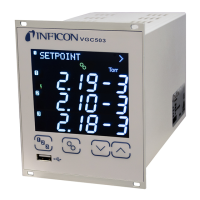
SETPOINT >I The switching function parameter group is used for
displaying, editing and entering threshold values and
assigning the two (VGC501), four (VGC502) or six
(VGC503) switching functions to a measurement
channel.
SP1-CH I Configuration of switching function 1
SP1-L I Switching function 1 lower threshold
SP1-H I Switching function 1 upper threshold
SP2-CH I Configuration of switching function 2
SP2-L I Switching function 2 lower threshold
SP2-H I Switching function 2 upper threshold
SP3-CH I Configuration of switching function 3
(VGC502/503 only)
SP3-L I Switching function 3 lower threshold
(VGC502/503 only)
SP3-H I Switching function 3 upper threshold
(VGC502/503 only)
SP4-CH I Configuration of switching function 4
(VGC502/503 only)
SP4-L I Switching function 4 lower threshold
(VGC502/503 only)
SP4-H I Switching function 4 upper threshold
(VGC502/503 only)
SP5-CH I Configuration of switching function 5
(VGC503 only)
SP5-L I Switching function 5 lower threshold
(VGC503 only)
SP5-H I Switching function 5 upper threshold
(VGC503 only)
SP6-CH I Configuration of switching function 6
(VGC503 only)
SP6-L I Switching function 6 lower threshold
(VGC503 only)
SP6-H I Switching function 6 upper threshold
(VGC503 only)
< I One level back
The VGC501 has two, the VGC502 has four and the VGC503 has six, switching
functions with two adjustable thresholds each. The status of the switching functions
is displayed on the front panel and can be evaluated via the floating contacts at the
CONTROL, respectively RELAY connector.
• VGC501: CONTROL connector (→ 21)
• VGC502, VGC503: RELAY connector (→ 22)
4.5.1 Switching Function
Parameters
Parameters in this group
 Loading...