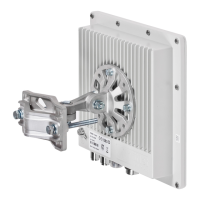
2 Equipment Positioning Guidelines during InfiNet
Wireless R5000 Installation
2.1 Antenna Placement
When selecting an antenna placement for PtP link, in order to obtain the maximum link range
and performance, LOS must be clear for the path between the two antennas.
The radio beam is an invisible form of electromagnetic wave propagation and is not as thin as,
for example, a light (or laser) beam. The main energy in a radio beam is concentrated along the
straight line between the two antennas, inside an area the shape of an ellipsoid (or a rugby
ball). This area is called a 1 Fresnel zone and its exact form and size depends upon the
st
frequency and the signal propagation path length.
If most of the 1 Fresnel zone is obstructed, a major part of the radio wave’s electromagnetic
st
energy is lost, which leads to a severe signal quality degradation and, as a result, to decreased
coverage range or performance.
Below is an incomplete list of possible obstructions on the signal propagation path:
Neighboring buildings
Trees
Bridges
Power lines
To obtain the best results, it is necessary to perform a precise analysis of the signal
propagation path and possible obstructions that may cover the 1 Fresnel zone.
st
Here are some general recommendations for antenna placement:
NOTE
For radio planning and path profile analysis, both the terrain model and clutter layer
of the area are required. These are typically provided by professional mapping
vendors. For details, please contact InfiNet Wireless.

 Loading...