InfiNet Wireless Quick Start Guide
Copyright © 2004-2009 by InfiNet Wireless Limited.
which will mean that the network 9.2.8.0/24 is accessible via 10.10.10.2
address.
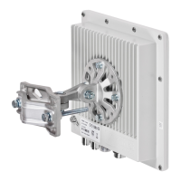
At this point, you can reach (e.g. ping) remote’s eth0 interface both from
one unit to another.
Figure 21. Pinging remote’s Ethernet
The next step is to make you Laptops/PC/LAN “see” each other.
If you connect two PC/Laptops (for example, Windows-basic) two options are
available in this case:
1. Write a route to the corresponding Ethernet network at the opposite side of
the link. In order to do this, go “Start->Run” and run “cmd” – Command
Line. At the BS computer you should write the following:
route add 9.1.8.0 mask 255.255.255.0 9.2.8.1
This means that when an IP-packet goes from the computer connected to
your BS device to the computer at the CPE side, it will go to the BS Ethernet
interface. In the unit, according to the routing tables formed using RIP
protocol, the packet will be sent via radio to the CPE unit. After that, CPE
unit will look up in its routing tables and send the packet through its
Ethernet interface to the remote computer.
At the CPE computer you should perform similar actions. Go “Start->Run”
and run “cmd” command. Type the following:
route add 9.2.8.0 mask 255.255.255.0 9.1.8.1
Now we provided connectivity between two computers.
All routes in Windows that are specified using route command have
power until next reboot of the computer (special parameter “-p”
should be used to make a route permanent). To see the routing table
in Windows “route print” command should be used.
2. The second option is to specify a default gateway for the PC/Laptop which
is going to be an Ethernet interface of the connected unit. You can specify
default gateway parameter in the window shown on Figure 14. Please refer.
For the BS side it will be 9.2.8.1, for CPE – 9.1.8.1
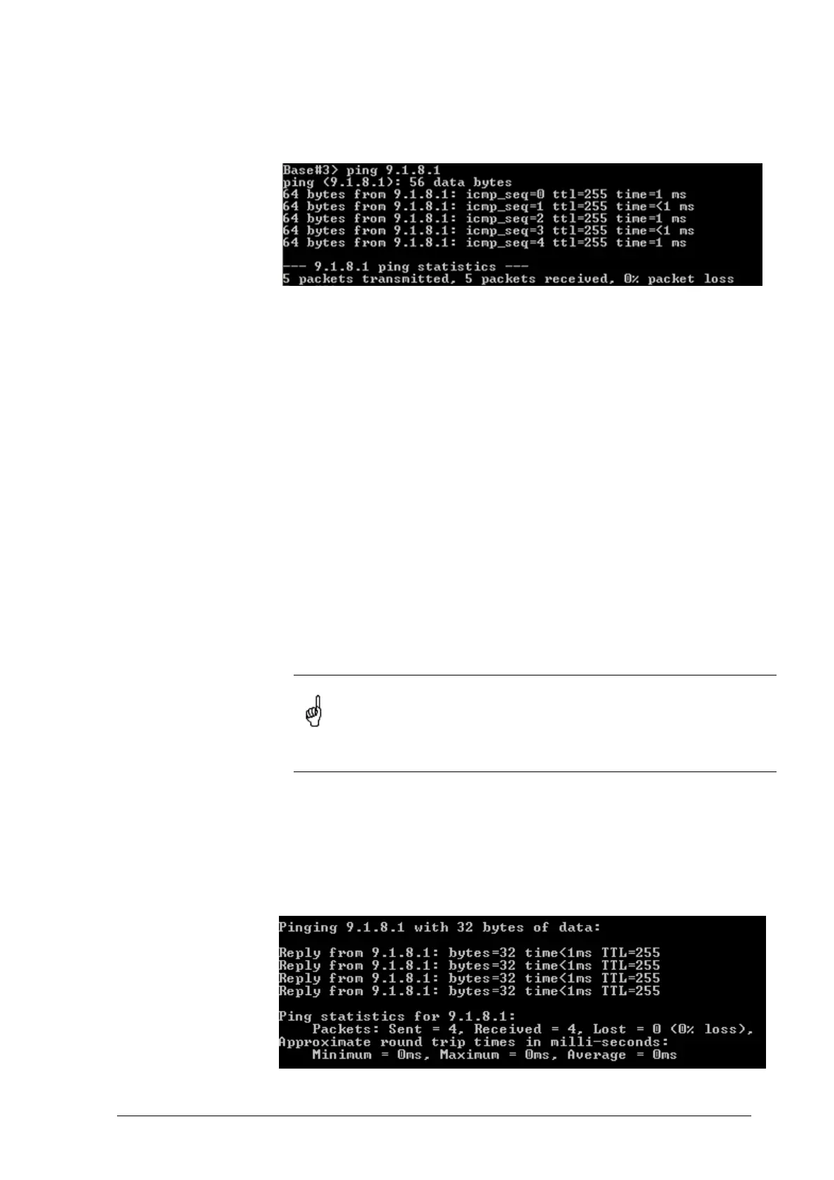
In order to make sure that your PC/Laptops are connected, you can ping one
side from the other one. For example, from one PC/laptop (located at one side of
the link) we are pinging remote computer at the opposite side (Figure 28)
Figure 22. Pinging remote computer
 Loading...