Do you have a question about the Infinity Kappa Subwoofer and is the answer not in the manual?
Check your subwoofer carefully for damage in transit and report it immediately.
Follow all safety and operating instructions, heed warnings, and avoid hazards like water and overloading.
Warnings about electric shock, not opening the unit, and exposure to rain or moisture.
Always turn off equipment when changing cables or plugs to prevent transients and electrical energy.
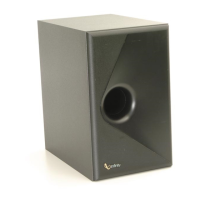
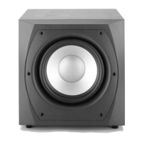
Place subwoofer 2-3 feet from TV/computer. Experiment with placement for optimal bass response.
Directing the port to the side may improve bass blend. Adjusting proximity to walls affects bass output.
Table outlines connection methods for different system types; never connect both speaker and line input.
Connects to systems without subwoofer or pre-out/main-in connectors using speaker outputs.
Connects preamp output to subwoofer line input and subwoofer line output to power amplifier input.
Connects AV receiver subwoofer output via Y-connector to subwoofer line input; set speakers to SMALL.
Set Bass Optimisation to OFF, Volume to minimum, Crossover fully clockwise before powering on.
Adjust Volume for pleasing blend; adjust Crossover to control upper frequency limit for optimal bass.
Experiment with various locations for optimal low-frequency enhancement and blend.
Avoid setting Volume control fully clockwise; it may indicate system imbalance or incorrect placement.
Turn off power, disconnect cord, and replace fuse with exact same value (2.5A, slow blow, 250V).
Kit includes Sound-Level Meter, Test CD, Instructions, Measurement Templates, Width Selector, and Adjustment Key.
Optimizes subwoofer response to room acoustics for dramatically improved sound via parametric equalization.
Instructions for performing tests, assuming speakers are installed and system is interconnected.
Ensure R.A.B.O.S. controls are clockwise/off, tone controls flat, bypass effects, set speakers to SMALL.
A handheld device to measure sound levels, indicated by an LED bar graph for power, signal, and battery.
LED indicators for Under-range, Measurement In-range, Over-range, and Low Battery status.
Set system volume using R.A.B.O.S. Test CD Track 2 to achieve -10 dB on the RSLM.
Use Track 3 to step through tones, adjust subwoofer level control for 0 dB peak on RSLM.
Mark the intersection of frequency (X-axis) and relative level (Y-axis) on the template for each test tone.
Mark the bottom frame of the template if the green 'ON' LED is illuminated, indicating sound level is too low.
Connect the plotted data points to make interpretation of the response graph easier.
Enter equalizer settings (Frequency, Level, Width) into the template fields after measurements.
Adjust equalizer frequency from 20Hz-80Hz and Width from 5%-50% of an octave.
Position Selector over template, aligning its center rivet with the response peak for best fit.
Slide Width Selector tab to match the response data, read the width percentage from the pointer.
Common result; apply Width Selector to peak, determine frequency, width, and level for correction.
Table shows switch positions for Frequency, Level, and Width adjustments.
Cue Track 51 and 52 to adjust system volume and subwoofer gain to -10 dB on RSLM.
Address boomy bass by isolating turntable and CD players from vibrations.
Product compliance with technical standards EN 55013, EN 55020, EN 55022, EN 61000-3-2, EN 61000-3-3.