Do you have a question about the Infortrend S12 Series and is the answer not in the manual?
Instructions for installing and operating the EonStor DS RAID system and JBODs.
Recommends using Infortrend certified components for compatibility and quality.
Details Fibre-Host RAID models, listing host port types and showing port locations for different speeds.
Details SAS-Host RAID models, listing host port types and showing port locations for 6Gb/s SAS and iSCSI ports.
Lists requirements for hardware installation: static-free environment, component check, drives, cabling, and rack installation.
Provides an overview of the system installation steps: unpacking, rack mounting, component installation, cabling, and powering up.
Lists factors to consider when purchasing and installing hard drives: capacity, profile, and drive type.
Explains the installation of the Cache Backup Module (CBM) on the controller before rack-mounting.
Provides steps to remove the RAID controller from the chassis by loosening screws and pushing ejection levers.
Details the procedure for installing the Battery Backup Unit (BBU) Type I into the controller.
Provides a pre-power-on checklist for CBM, hard drives, drive trays, cables, and ambient temperature.
Explains the status LEDs on the LCD keypad panel (PWR, BUSY, ATTEN) and their meanings.
Details the status LEDs for controller modules: Ctrl Status, C_Dirty, Temp LED, and CBM Status LED.
Explains PSU and Cooling fan LEDs, indicating power status and fan failure.
Lists system monitoring features: firmware access via terminal, and SANWatch GUI for monitoring.
Provides steps to restore default settings for dual-controller models, including stopping I/O and exporting NVRAM.
Warns against removing failed components without replacements and lists replaceable components: controller, memory, CBM, PSU, and hard drive.
Provides instructions and warnings for replacing or upgrading controller modules, emphasizing firmware matching.
Lists indicators for detecting a failed PSU: PSU status LEDs, audible alarms, firmware utility, and SANWatch.
Lists slide rail kits for RAID/JBOD models, categorized by model numbers for easy identification.
Lists warnings for proper enclosure installation and functionality, including component checks and environmental conditions.
Details accessories for IFT-9272 slide rail kits, designed for 2U enclosures and specific rack depths.
Details installing IFT-9272 rack mount slide rails, attaching clip nuts to rack posts.
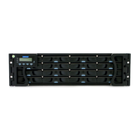
Details accessories for IFT-9273 slide rail kits, designed for 3U enclosures and specific rack depths.
Details installing IFT-9273 slide rails, inserting clip nuts, and determining slide rail length.
Details accessories for IFT-9279CSlider36 slide rail kits, designed for 36” deep racks.
Details installing IFT-9279 slide rails, securing rails to posts, and placing cage nuts.
| Model | S12 Series |
|---|---|
| Category | Storage |
| Drive Bays | 12 |
| Supported Drives | 3.5-inch SATA HDDs |
| Interface | SATA |
| RAID Levels | 0, 1, 5, 6, 10, 50, 60 |
| Host Connectivity | SAS |
| Host Interface | SAS |
| Controller | Dual active-active controllers |
| Power Supply | Redundant power supplies |
| Cooling | Redundant cooling fans |
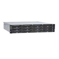
| Form Factor | 2U Rackmount |