INFOSEC UPS SYSTEM – 15, Rue du Moulin – 44880 Sautron – France – www.infosec-ups.com
Hot Line Tel : +33 (0)2 40 76 15 82 – fax : +33(0)2 40 94 29 51 – hotline@infosec.fr – 02 19 AA 59 203 07
Interface and Communication
This UPS comes equipped with various communication devices. Please refer to chapter 4 Interface and
Communication for further details.
Power Stage/Module
Each power stage/module includes a power factor correction rectifier, a battery charger, an inverter and
control circuit.
Air enters the power stage/module through the front grills and exhausted
through rear of the module. Please do not block the ventilation vent port.
There are three DIP switches for power stage/module address setting. In the
same cabinet, each power stage/module ID MUST be exclusive. Please refer
to Table 2-1 Power Stage/Module ID
When there is no AC input, use this button to start the battery power for the
UPS.
The power stage/module is in fault condition.
The power stage/module IDs in conflict.
The power stage/module normally works as a slave
unit.
The power stage/module normally works as a master
unit.
The CAN BUS communication does not work.
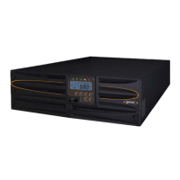
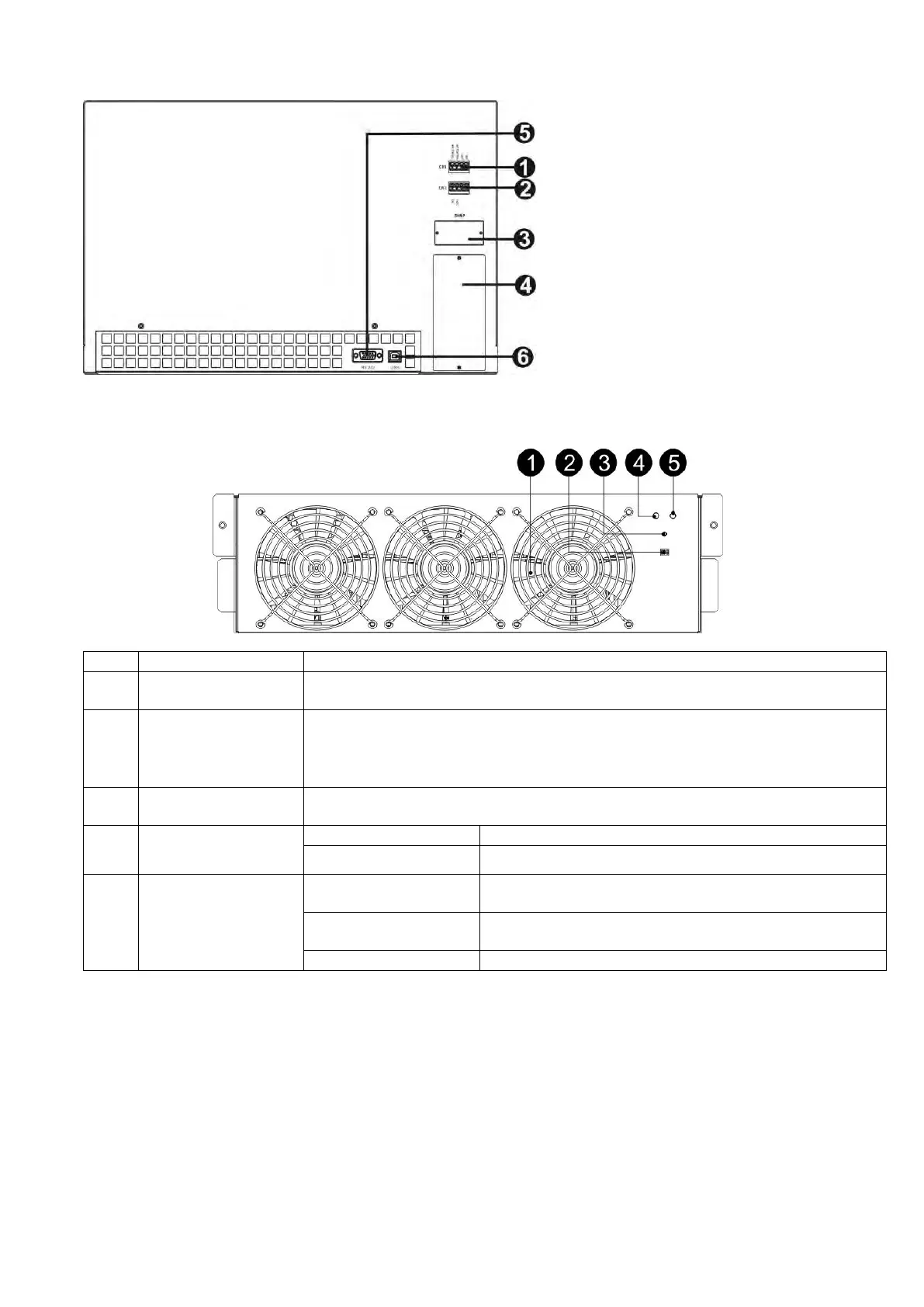
2-3. Rear Panel View
There are various breakers located on the rear panel of the UPS.
1. Dry contact port X1
2. Dry contact port X2
3. SNMP slot (SNMP card optional)
4. Extended communication
slot(Extra Comm. card optional)
5. RS-232 port
6. USB port
 Loading...