2
INFOSEC UPS SYSTEM - 4, rue de la Rigotière - 44700 Orvault - FRANCE - www.infosec-ups.com
Hot Line – Tel + 33 (0)2 40 76 15 82 - Fax + 33 (0)2 40 94 29 51 - hotline@infosec.fr – 04 11 AA 59 201 17
GENERAL INDEX
1 INTRODUCTION .............................................................................................................................. 4
1.1 Using this manual ............................................................................................................................ 4
1.2 Symbols and conventions .................................................................................................................. 4
1.3 For further information and/or help ................................................................................................... 4
1.4 Safety and first aid ........................................................................................................................... 4
2 QUALITY AND STANDARD GUARANTEE .......................................................................................... 5
2.1 Standard ......................................................................................................................................... 5
2.2 Environment .................................................................................................................................... 5
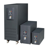
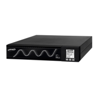
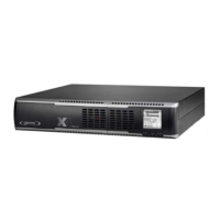
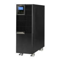
3 PRESENTATION ............................................................................................................................... 6
3.1 Views. ............................................................................................................................................. 6
3.1.1 Equipment. ............................................................................................................................. 6
3.1.2 Diagram keys. ....................................................................................................................... 10
3.2 Definition and structure. ................................................................................................................. 11
3.2.1 Structural diagram. ................................................................................................................ 11
3.3 Operating principle. ........................................................................................................................ 12
3.3.1 Normal operation, (). .......................................................................................................... 12
3.3.2 Operation with mains failure, (). ........................................................................................... 12
3.3.3 Operation with inverter not active, (). .................................................................................. 12
3.3.4 Operation in manual bypass, (). .......................................................................................... 12
4 INSTALLATION .............................................................................................................................. 13
4.1 Important safety instructions. ......................................................................................................... 13
4.1.1 Batteries. .............................................................................................................................. 13
4.1.2 Account access. .................................................................................................................... 14
4.2 Equipment Reception. .................................................................................................................... 16
4.2.1 Unpacking and content checking............................................................................................. 16
4.2.2 Storage. ............................................................................................................................... 16
4.2.3 Transport to location. ............................................................................................................ 17
4.2.4 Location. .............................................................................................................................. 17
4.3 Connections. ...............................................................................................................................
... 17
4.3.1 Mains terminals (X1 to X4). .................................................................................................... 17
4.3.2 Independent static bypass line connection, terminals (X14 to X17). Only in versions M4T-B. ........ 18
4.3.3 Output, terminals (X6 to X9). ................................................................................................. 19
4.3.4 UPS connection to each in-cabinet battery pack, terminals (X11, X12, X23) & (X47, X48, X49). .... 19
4.3.5 Main protective earthing terminal (
) & protective earth bonding terminal ( ). ......................... 20
4.3.6 COM port to relay. Connector (X32). ....................................................................................... 21
4.3.7 Port COM RS-232 & RS-485. Connector (X32). ......................................................................... 21
4.3.8 EPO terminals (X50). ............................................................................................................. 22
5 OPERATION ................................................................................................................................... 23
5.1 Start up ......................................................................................................................................... 23
5.1.1 Control before start up. ......................................................................................................... 23
5.1.2 Start up procedure. ............................................................................................................... 23
5.2 Complete UPS shutdown. ................................................................................................................ 25
5.3 Emergency power off (EPO) operation. ............................................................................................ 25
5.4 Bypass manual switch (MAINTENANCE). .......................................................................................... 26
5.4.1 Operating principle. ............................................................................................................... 26
5.4.2 Transfer to maintenance bypass. ............................................................................................ 26
5.4.3 Transfer to normal operation .................................................................................................. 26