24 Installation
Fire alarm and extinguishing system
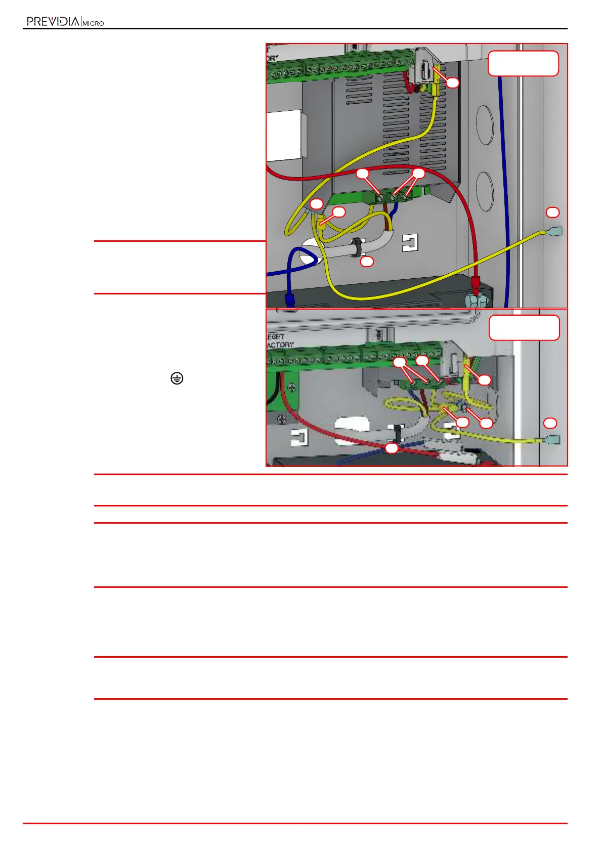
1. Connect the mains power supply to the
terminals on the power-supply module ([A],
paragraph 2.2 - [S]).
For a safety standards compliant system, the
Line must be connected to terminal “L”, the
Neutral conductor to terminal “N”.
The power supply to the control panel must
come directly from a reserved line of the
electric distribution panel. The line must be
protected by a sectioning device which
complies with local safety regulations, fire
codes, laws and bylaws in force.
The power source must be provided through a
bipolar protection device.
Note: As a further safety measure, the
electrical system of the building
must be protected against overload
and short-circuit.
2. Crimp the earth line wire to the eyelet terminal
[B]
.
3. Attach the wire with the eyelet to the control
panel using the ground connection screw [C].
4. Ensure that the terminal “ ” of the power
supply module [D]], the motherboard [E] and the
front plate [F] of the cabinet are connected to
earth system.
Attention: The protective earthing system must be compliant with the local safety regulations, fire codes, laws
and bylaws in force.
Note: A protective earth connection ensures that all exposed conductive surfaces are at the same electrical
potential as the earth surface, in order to avoid the risk of electrical shock if a person touches a device in
which an insulation fault has occurred. In the event of an insulation fault, a protective earth connection
will generate a high fault current which in turn will trigger an overcurrent protection device (fuse) and
disconnect the power supply.
5. Ensure that low-current safety or signal lines DO NOT come into contact with points with potentially dangerous
currents.
Using a plastic cable tie, bunch the wires together and secure them to one of the wire hooks on the back of the
cabinet [G].
Note: The connection wires (to the mains supply and also any other wires inside the cabinet) must be secured
to the cable hooks on the back plate by means of plastic cable ties. Use cable with double isolation for
the connection to the electrical mains.
3.3.2 Connecting the batteries
The metal cabinet of the control panel provides housing for two 12V, 7 Ah lead batteries for the small version and 17 Ah
for the large version. The two batteries must be connected in series, in such way as to supply 24V.
The backup power batteries are not included.
1. Insert the batteries into the battery compartment inside the cabinet (paragraph 2.2 - [B1]).
C
B
D
E
F
A
G
Previdia Micro in
large cabinet
D
E
F
A
C
B
G
Previdia Micro in
small cabinet