Installation manual
Installation 25
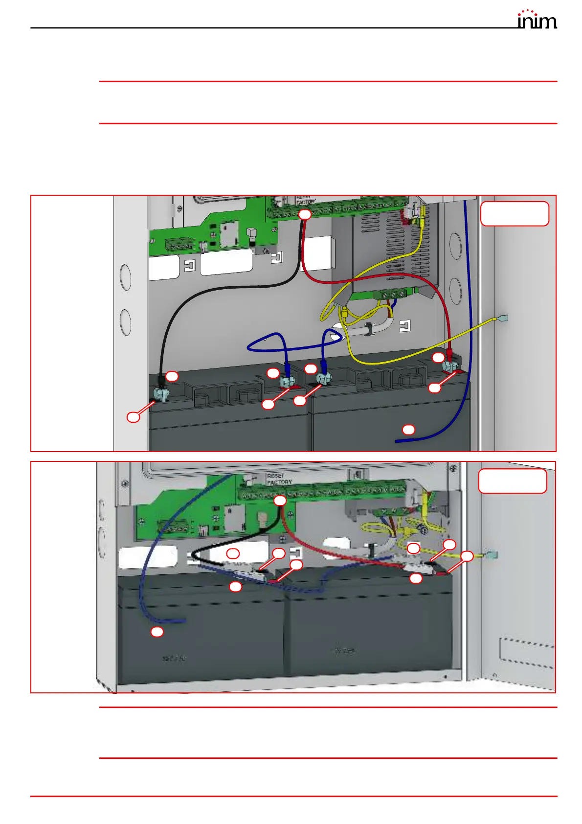
2. Using the battery wire ([A]), connect the batteries together.
3. Connect the wire coming from the power supply ([B] paragraph 2.2 - [V]) to the battery terminals ([C]).
Attention: Ensure that the polarity is correct.
Red - positive
Black - negative
The connection of the batteries before the mains voltage is present will not activate the system. Once the mains voltage is
supplied, the power-supply module will connect the batteries automatically and initialize the circuits which manage them.
4. Position the thermal probe (paragraph 2.2 - [W]).
The thermal probe must be positioned on the side of the battery and held in place by a strip of tape ([D]).
Note: The installer must use only valve regulated lead-acid batteries (VRLA) for stationary use, compliant with
IEC 60896-21 and IEC 60896-22 standards. Such batteries must have a V-1 or higher firestop casing.
For the internal clock battery replacement, the installer must use only non-rechargeable CR2032 lithium
batteries compliant with IEC 60086-4 standard.
C
A
-
A
B
C
D
+
-
+
Previdia Micro in
large cabinet
A
A
D
B
C
C
-
+
-
+
Previdia Micro in
small cabinet