MODEL 3000 / ACCESS 4000. CE Installation Notes.
14
CABLE TYPES
- TWISTED PAIR Cable MUST be used to connect the LAN.
Multi-strand wire is preferred for terminating into the screw terminal connectors.
Two pair Telephone or LAN cable is suitable as it provides all 4 conductors required.
One pair for “A” & “B”, and the other for “POS” & “NEG”. Unshielded cable is quite acceptable, however, in situations
where electrical storms or high levels of electrical interference are a problem, shielded 2 pair cable may be used.
Examples of suitable 2 pair cables:
Unshielded. Figure 1. Shielded (All Multistrand) Figure 2.
Olex TJC590AA002 Olex JEIP87AA002 Belden 8723 * † 3 Pair.
Tycab TIC6105 † Tycab DPF4702 Tycab DQQ47025 * ‡ Multistrand (7/0.2).
MM MegaTwistpatch ‡ MM B2002CS Garland MCP-2S * Indivually screened pairs.
Category 5. Electra EAS7202P / 7302P Electra EAS16202P
- If SHIELDED CABLE is used, DO NOT use the shield as a negative connection & do not allow the shield to make contact
with Negative, Ground, or any other wiring or metalwork within the system. Shields should only be terminated to a
Protective Earth at ONE END of the cable. ¶ See “System Earthing” below. If no suitable earth point is available at a
module location, the shield can be looped back to the shield of the previous length of cable. ·
- LAN POWER CABLING. Separate heavy duty Figure 8 cable ( 24 / 0.20 recommended) should also be run for “POS” &
“NEG” over longer distances if used for powering modules. e.g. LCD Terminals. Figure 3.
LAN “POS” current required: Max. Cabling Length for LAN +ve (POS) & GND (NEG)
Twisted pair Fig 8. 14 / 0.20 Fig 8. 24 / 0.20
60mA (e.g. 1 LCD Terminal) 200 metres 400m 640m
120mA (e.g. 2 LCD Terminals) 100 metres 200m 320m
180mA (e.g. 1 Reader Module - Reader pwr not incl) 62metres 130m 210m
250mA (e.g. 4 LCD Terminals) 50 metres 100m 160m
500mA (e.g. 8 LCD Terminals) 25 metres 50m 76m
Remember to allow for any extra current required by Detectors, Auxiliaries, Readers, etc:
NOTE: Lock strikes must not be powered from the LAN.
Relay (1A contacts) approx. 25mA Small Proximity reader (~10cm read range) ~50 to 120mA
Relay (5A contacts) approx. 45mA Standard Prox reader (~15cm read range) ~120 to 180mA
PIR 15 to 25mA typical. Magnetic Swipe reader. ~15mA
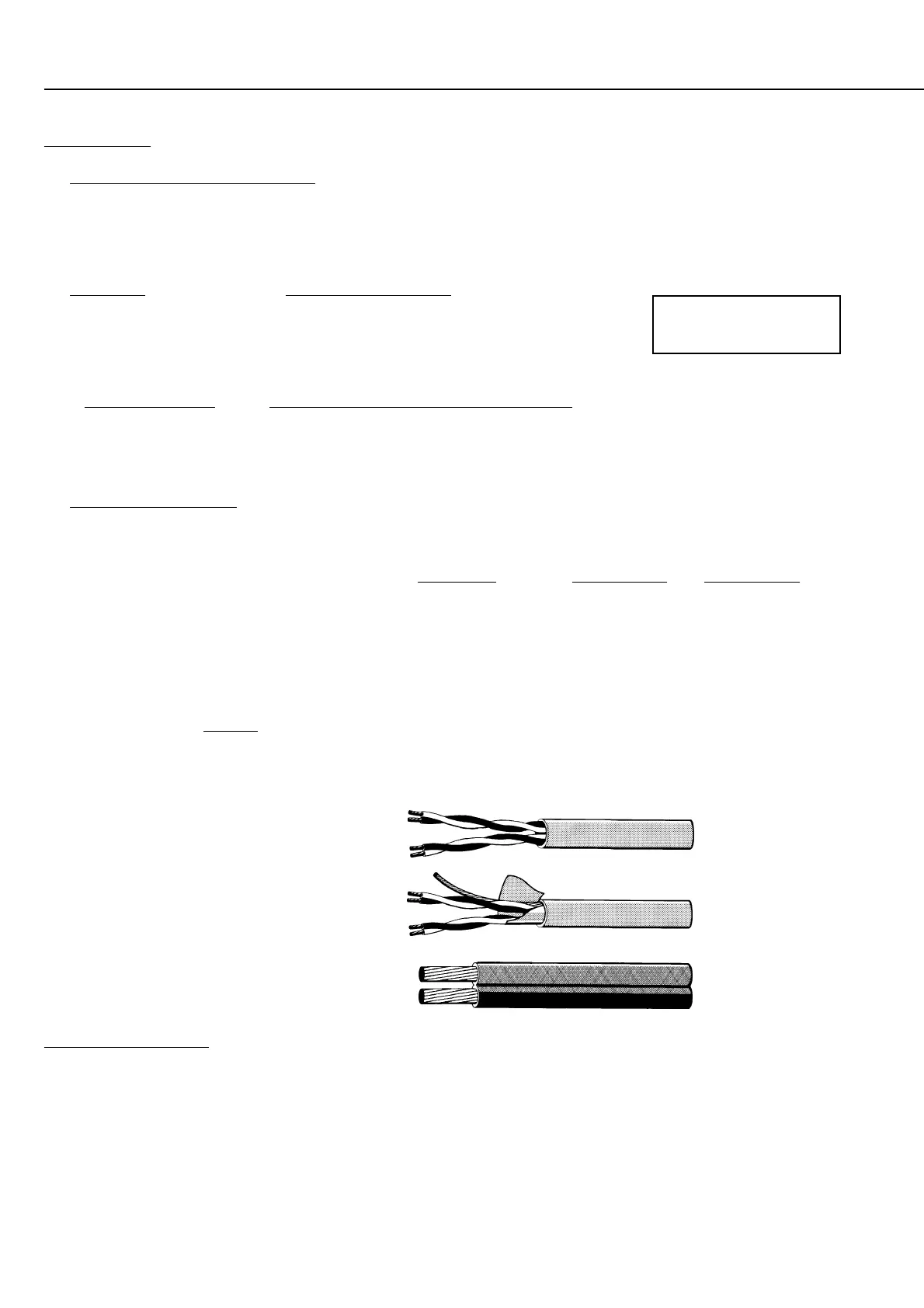
Figure 1.
Twisted pair communications cable.
Figure 2.
Shielded, twisted pair
communications cable
Figure 3.
Heavy duty Figure 8 cable. 24 / 0.20
Used for LAN +ve & GND on long cable runs.
SURGE PROTECTION.
- In multi-building installations and on longer cable runs, shielded cable may be used to provide added protection against
voltage surges.
- Each individual shield should be terminated to a Protective Earth point such as an earth stake, building earth (metal building
framework) or water pipe. ¶ It is very important to ensure that the shield makes no contact with Negative, Ground or any
other wiring within the system.
- LAN Isolator/s can also be included in a Surge protection scheme to electrically isolate different sections of the LAN at the
point where LAN cabling enters/exits each building, or on cable runs that are more exposed to voltage spikes or surges.