MODEL 3000 / ACCESS 4000. CE Installation Notes.
4
Electrical AC Mains Power connection.
In countries where the module is supplied without a mains power cord, a suitable mains power cord for connection to the 240V
AC Mains supply must be installed by a suitably qualified electrician or technician.
1. Strip 30mm of the sheath from the end of the power cord. Trim 5mm from the ends of the Active and Neutral conductors so
that the Earth conductor remains slightly longer.
2. Strip 5mm of insulation from each of the conductors and fit the conductive sleeves provided to the exposed ends of the
conductors to protect the integrity of the wire strands.
3. Feed at least 150mm of the power cord through the AC mains cable entry hole from the rear (underside) of the chassis.
4. Terminate the power cord in the terminal and fuse block as illustrated in Diagram 1 below. (Note that the Active wire is
always connected into the termination nearest to the fuse)
5. Determine the appropriate length of power cord between the terminal block and the cable entry hole. (Approx. 100mm)
Working from the rear of the chassis, fit the plastic grommet (supplied) around the power cord and apply pressure to both sides
of the grommet to clamp the cable. The grommet can now be inserted into the AC mains cable entry hole.
6. When fitting the cover, ensure that the special AC Powercord “D” bung is fitted to the cable entry cutout in the cover where
the AC Powercord enters the enclosure. Standard “D” bungs must be fitted to all other unused cable entry cutouts.
IMPORTANT NOTE: An AC Mains socket-outlet shall be installed near the equipment and shall be easily accessible for
connection of the mains power cord.
Mounting the Unit. See Diagram 2.
1. Installation environment should be maintained at a temperature of 0º to 40º Celsius and 15% to 85% Relative humidity (non-
condensing)
2. CE Control Modules are supplied in metal enclosures which must be secured to a flat, vertical surface using fasteners through
the four “keyhole” mounting holes in the chassis.
3. When mounting this product onto flammable surfaces, a fire protection backplate MUST BE INSTALLED. The mounting
holes in the backplate align with the mounting holes in the chassis so no additional mounting hardware is required. Standard
“D” Bungs must be fitted to all unused cable entry cutouts.
This backplate is available from your distributor. Please quote part number 925010.
4. The tamper switch bracket must be positioned through one of the slots in either side of the chassis and under the base of the
chassis, before the chassis is secured to the wall.
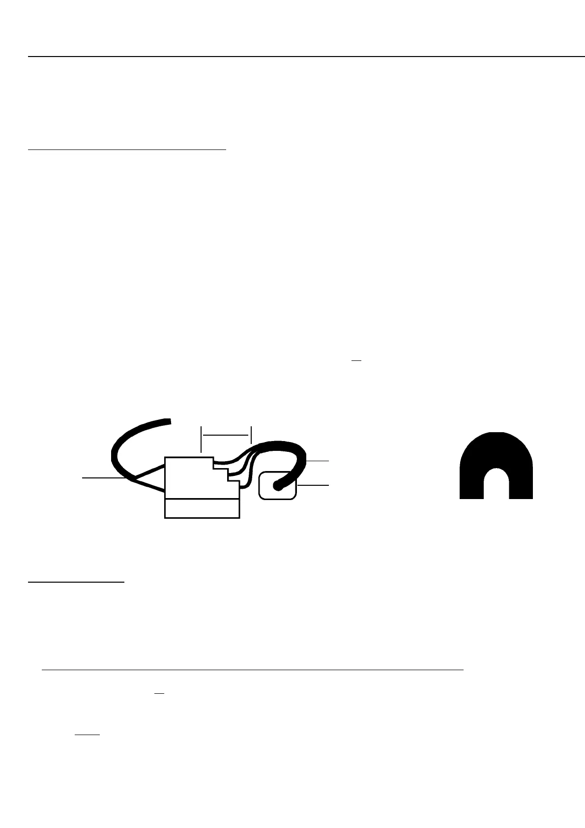
Transformer
input connection.
Power Cord
AC Mains cable entry
hole & Plastic Grommet.
Neutral
Earth
Active (Live)
Fuse. 500mA
8AG (25mm)
Diagram 1.
25mm
INSTALLATION AND SAFETY INSTRUCTIONS
Special “D” bung for
AC Power cord entry.