Revision 4.02 June. 2000 5
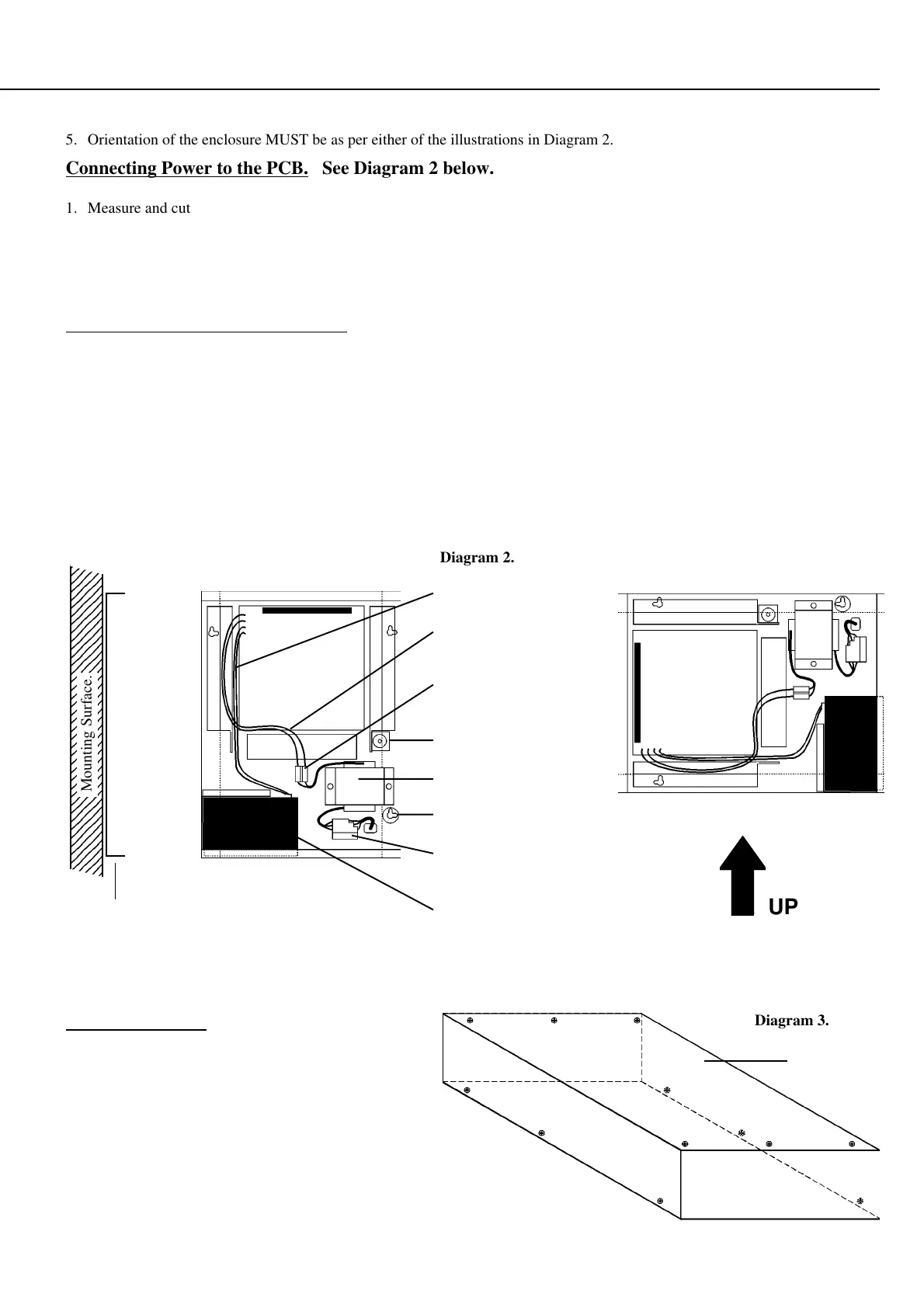
Battery connections
16.5V AC Power
connections to PCB.
Transformer output
terminal block.
Tamper switch & bracket
AC Mains Transformer
Mounting Holes (x 4).
Terminal block and fuse.
AC Mains Input.
12V, 6.5AH Battery
Fitting the Cover.
In order to comply with regulations, all twelve (12) of
the screws provided to fix the cover to the chassis
must be tightly secured. Three screws are located on
each of the long sides, and at each end of the top of
the cover as illustrated in Diagram 3 opposite.
Fire Protection Backplate option.
(Side View)
234
234
234
234
234
234
234
234
234
234
234
234
234
234
234
234
234
234
234
234
234
234
234
234
234
234
234
234
234
234
234
234
234
234
234
234
234
Mounting Surface.
Diagram 2.
Diagram 3.
UP
5. Orientation of the enclosure MUST be as per either of the illustrations in Diagram 2.
Connecting Power to the PCB. See Diagram 2 below.
1. Measure and cut two appropriate lengths of insulated cable to connect between the AC mains transformer output terminal
block (A) and the “AC” Input connections on the PCB (B).
2. Strip 5mm of insulation from both ends of the cables and terminate into the transformer output terminal block and then into the
“AC” Input connections on the PCB. The cables may be routed underneath the chassis to avoid interference with other cables.
Connecting the Battery to the PCB. See Diagram 2 below.
1. Measure and cut two appropriate lengths of insulated cable to connect between the “+B” and “-B” connections on the PCB (C)
and the Battery terminals (D).
2. Strip 5mm of insulation from both ends of the cables and terminate one end into the “+B” and “-B” connections on the PCB.
IMPORTANT NOTE: There are two terminals provided for each of the “+B” and “-B” connections. Ensure that each cable is
connected to the correct terminal to avoid creating a short circuit across the Battery.
3. Terminate the other end of the cables into the 4.8mm Battery Terminal connectors supplied in the installation kit. The cables
may be routed underneath the chassis to avoid interference with other cables.
A
B
C
D
Top