Revision 4.02 June. 2000 15
EXPANDER
MODULE
T
CONTROL
MODULE
LCD
TERMINAL
LCD
TERMINAL
T
READER
MODULE
2000 metres max.
1500 metres max.
·
»»
EXPANDER
MODULE
CONTROL
MODULE
T
LCD
TERMINAL
LCD
TERMINAL
READER
MODULE
Total LAN cable in this section < 2000m (1955 m)
¸
º
T
T
400 m.350 m.
500 m.
5 m.
LCD
TERMINAL
100 m.
300 m.
LCD
TERMINAL
300 m.
¹
»
»
¹
LCD
TERMINAL
READER
MODULE
500 m.
600 m.
READER
MODULE
T
400 m.
LAN2 LAN3
LAN1
LAN Isolator
»
EXPANDER
MODULE
T
¼
LCD
TERMINAL
READER
MODULE
T
¼
600 m. 150 m. 500 m.
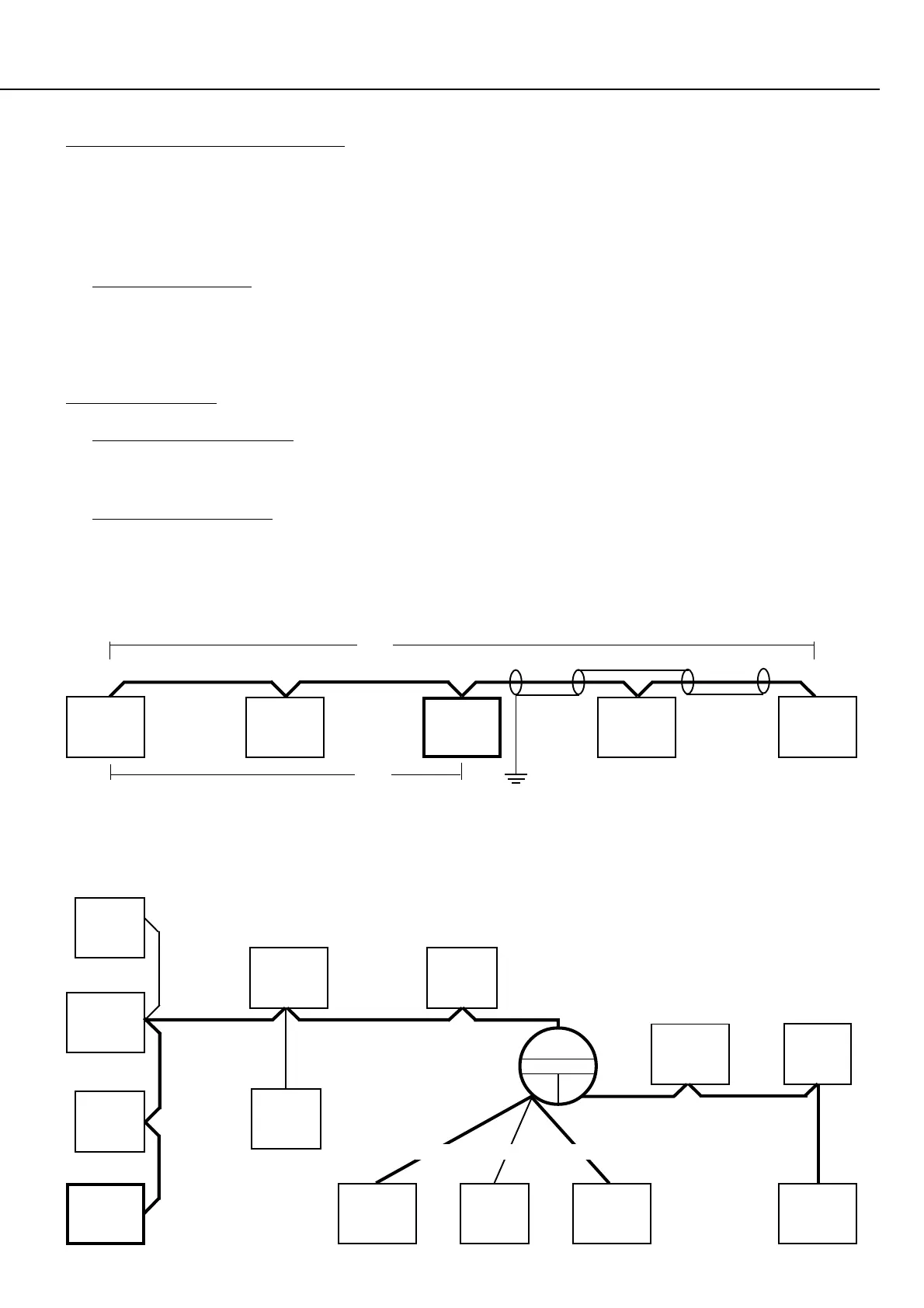
Figure 4.
Simple LAN configuration.
Figure 5.
Complex LAN configuration.
¸
SYSTEM CABLING CONFIGURATION Figure 4 & Figure 5.
- Avoid installing the LAN cable with mains power cables & any other cables likely to cause interference wherever possible
- No module is to be more than 1.5km (1500 metres) cable length from the Control Module OR from a LAN Isolator
“LAN 2” or “LAN 3” Port. ¸ (LAN Isolator/s can be used to extend the maximum cabling distance)
- TOTAL LAN CABLING in a system without LAN Isolators should not exceed 2000 metres, and/or 64 Modules. ¹
If the total amount of LAN cable will exceed 2000 metres, and/or there are more than 64 modules to be connected, LAN
Isolator/s must be used to separate the LAN system into sections and maintain optimum LAN performance. i.e. Include one
LAN Isolator for every 2000 metres of LAN cabling and/or for every 64 Modules connected. º
LAN TERMINATION Figure 4 & Figure 5.
- The LAN MUST be Terminated for optimum performance, by ensuring that the Termination Resistor (470 Ohm*) is “IN” on
the first and last modules in the LAN network. Terminated modules are indicated with a “T” on the illustrations. »
(Termination is put “IN” with a jumper link or a DIPswitch, depending on the module type) * See Note 1 on Page 15.
- MULTIPLE CABLE RUNS. In systems where there are multiple cabling runs going out from the Control Module or LAN
Isolator (i.e. “star” configuration), Termination is fitted on the modules at the end of the two longest runs. ¼
1500m.
from
“LAN3”
»