Revision 4.02 June. 2000 19
Designed & manufactured in Australia.
Disclaimer: 1. The manufacturer &/or it’s agents take no responsibility for any damage, financial loss or injury caused to
any equipment, property or persons resulting from the correct or incorrect use of the system or it’s peripherals. The purchaser
assumes all responsibility in the use of the system and it’s peripherals.
2. While every effort has been made to ensure the accuracy of this manual, the manufacturer assumes no responsibility or liability
for any errors or omissions. Due to ongoing development, this manual is subject to change without notice.
SYSTEM OPTIONS
A special Options Micro chip is used to enable certain system options and upgrade options in the Control Module.
The Chip is labelled U14 and is located between the Zone 9 to 16 Input connections and Links LK3 to LK6.
See PCB layout on page 11.
A range of standard Options Micro chips are available. These chips can be purchased and changed over by the installer at any time
to provide additional features.
The price of each Options Micro Chip Type will vary according to the feature/s that the chip will enable.
NOTE: If the additional feature required is new and was not available in the version of firmware currently in the Control Module,
then the Control Module firmware AND the Options Micro will need to be changed.
When purchasing 128k or 512k Memory expansion for the Control Module, an Options Micro chip will also be supplied to enable the
use of the additional memory.
IMPORTANT NOTE: When purchasing Memory expansion you must specify which product is being upgraded.
“3000” or “Access 4000”.
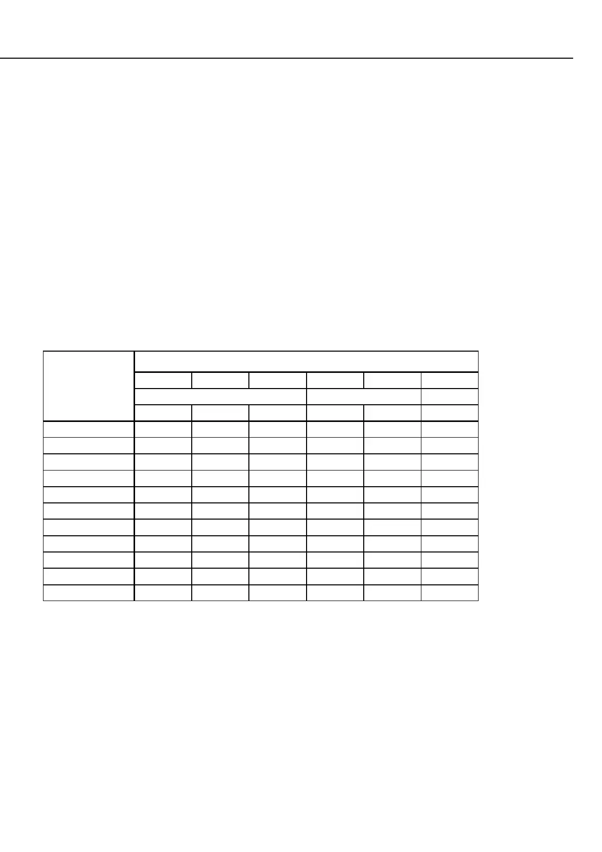
The table below shows the current range of Options Micro chips available.
This selection table may be expanded as further options become available.
* Factory fitted option for Model 3000. (32k Memory)
^ Factory fitted option for Model Access 4000. (128k Memory)
FEATURE
OPTIONS MICRO TYPE AND DESCRIPTION
1* 2 3 4^ 5
Standard 3000 Standard 4000
32k 128k 512k 128k 512k
Aircon. Control YES YES
Door Interlocking YES YES
ACCEPT YES YES YES YES YES
High Level Lift I/F
"Card only" Users YES YES
GSM SMS YES YES YES YES YES
Spare YES YES
Lift Access Control YES YES
128k RAM YES YES
512k RAM YES YES