MODEL 3000 / ACCESS 4000. CE Installation Notes.
6
604 Socket for
3000/4000 connection
Exchange Line
OR
Leased Line
604 Cable from
3000/4000 (Supplied)
604 Socket
to other equipment.
DIALER LINE ONLY
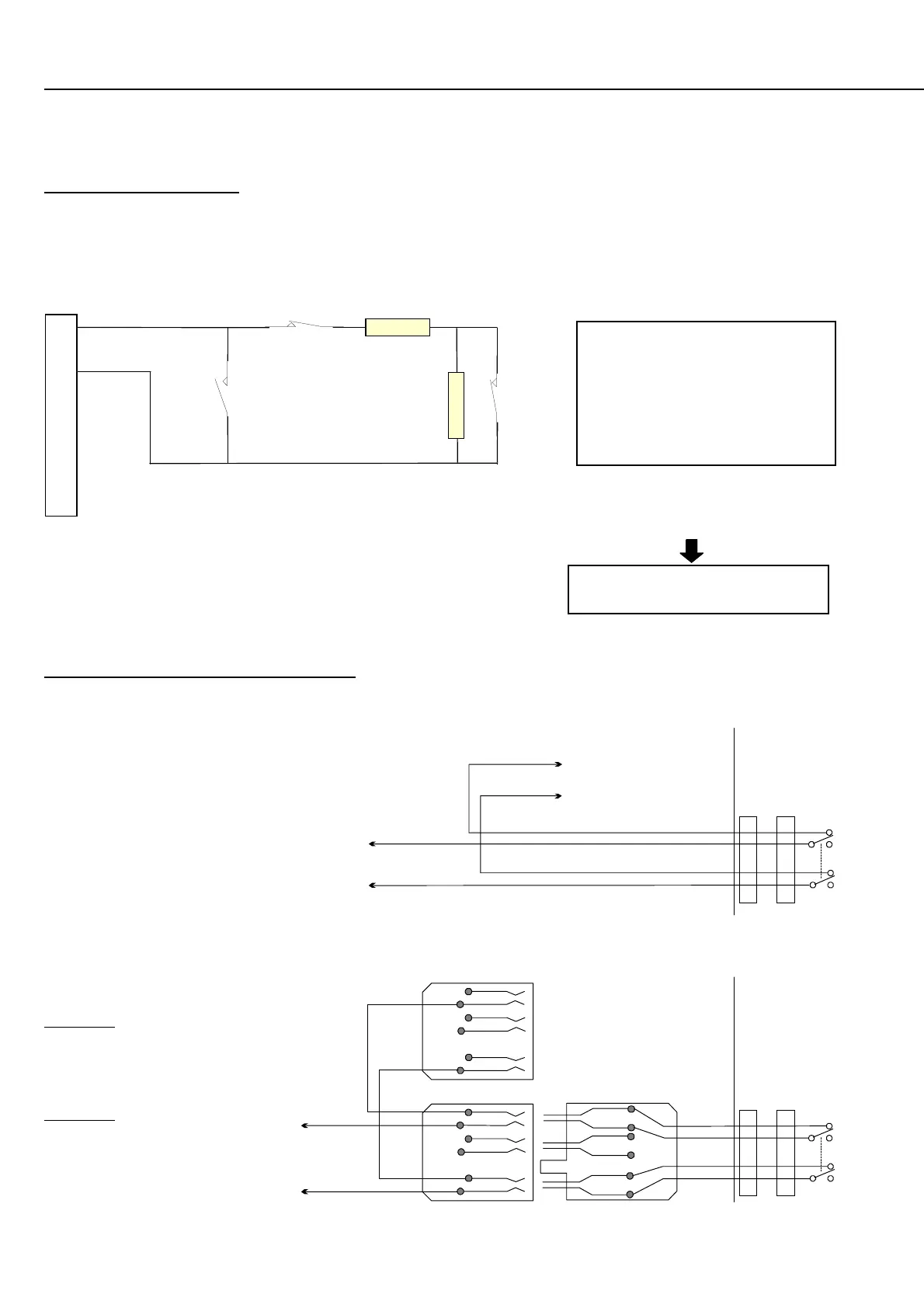
ZONE INPUT WIRING
Typical Detection devices with Normally Closed Alarm contacts and Normally Closed OR Normally Open Tamper Contacts are
wired as follows:
Detection devices with Normally Open Alarm contacts are wired in
exactly the same manner as above. When programming the Zone Input,
however, the option to “Swap Seal and Alarm conditions” must be set
to [Y]es.
E01:Z01 X S R A N T . .
Options -> n Y n n n n n n
INPUT STATES:
2k2 = Sealed
9k (2k2 + 6k8) = Unsealed
(or Alarm)
Open Circuit = Tamper
Short Circuit = Tamper
Z1 Z2 Z3
2k2
6k8
Norm.
Closed
Alarm
Contact
Norm . Closed
Tamper Contact
Norm.
Open
Tamper
Contact
Wiring Diagrams
Dialer Line
Phone Line IN: Pins 2 & 6
Phone Line OUT: Pins 1 & 5
Direct Line
For Direct Line formats
(e.g. EarthNet), the Leased
Line connects to Pins 2 & 6.
e.g.
TELECOMMUNICATIONS WIRING
Mode 3 wiring diagram for Dialer reporting formats. (e.g. Contact ID, 4+2, IRfast, etc.)
T11 or JP9
3000 / 4000
Control
Module
1
2
3
4
1
2
5
6
1
2
3
4
1
2
3
4
5
6
5
6
1
2
5
6
3
4
T11 or JP9
3000 / 4000
Control
Module
1
2
3
4
1
2
5
6
To Exchange Line
OR Leased Line
Connection to
other equipment.
DIALER LINE ONLY
Other equipment such as a telephone, fax
machine or answering machine may share
the Dialer line connection. If so, the
telecom connection must be wired as
shown to ensure that the system has
priority use of the line so that alarm
reporting is not compromised.
“604” Plug & socket wiring. (Australia Only)
NOTE: Cable supplied is a non-standard configuration
and is only suitable for use with this product.