Revision 4.02 June. 2000 7
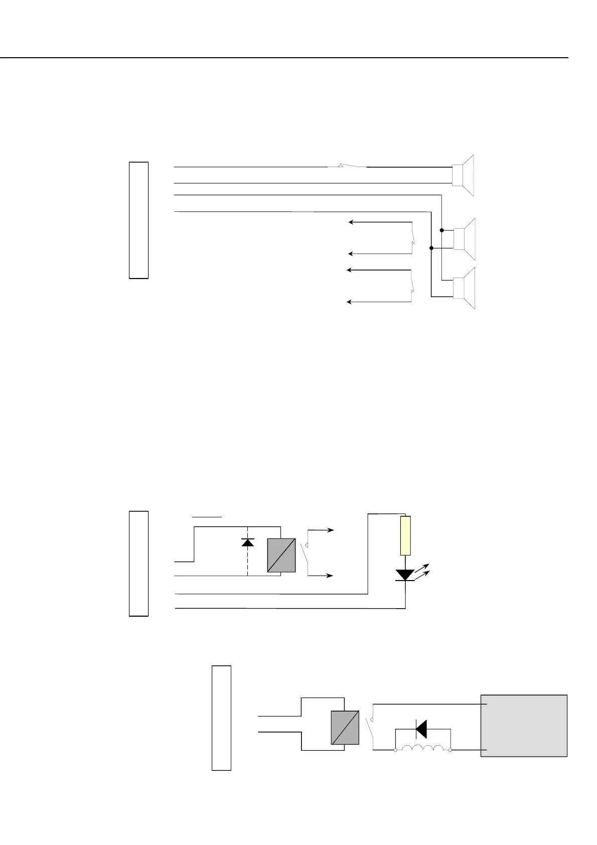
SIREN WIRING
Maximum of two 8 Ohm Siren speakers may be connected to each siren driver, wired in parallel. Norm. Closed Siren cover
Tampers may be wired in series with the speaker cable. This method utilizes the siren speaker circuit monitoring.
AUXILIARY WIRING
Rules for Auxiliary wiring on any module in the 3000/Access 4000 system.
- Auxiliaries 1 & 2 on the Control Module & Expander Modules can switch up to 500mA continuous and are suitable for
inductive loads provided that a clamp diode is fitted across the load as shown below.
- Max current on any other individual Auxiliary must be less than 200mA.
- On any module with Plug pack; Auxiliaries + LAN current + Detectors must be less than 700mA, or an external power supply
should be used.
- The Positive of the device must be wired to the Positive connection nearest the Auxiliary. i.e. On the same module.
- If an external power supply is used to power the device, a good common Negative connection MUST exist between the power
supply and the module.
- Clamp diode should be fitted across inductive loads. Cathode (bar) to +ve.
Locks are activated via a relay.
External power supply is used for lock
power to prevent voltage spikes
reaching the Concept equipment,
provide longer battery backup &
minimise the possibility of earth
loops.
NOTE: Auxiliary Current
< 200m A per Auxiliary.
+Ve connections to DET
+
ve
nearest
the Aux. output
Note LED
orientation.
1k2
1.2 k
Ω
current
limit resistor.
See notes.
AX2 AX1 S2 S1
+ +
Relay and Lock power
Connections M UST
be separated.
Clamp Diode MUST
be fitted across Lock.
Cathode to +ve.
o
o
POS
NEG
-
+
External
Pwr Suppl
(Batter
backed)
LockLock
Lock
Lock.
AX2 AX1 S2 S1
+ +
(Normally Closed)
Siren cover tamper
When wiring 2 speakers
in parallel it is best to
wire the cover tampers
to zone inputs & program
for tamper processing.
(Normally Closed)
Siren cover tampers
CABLE: 14/0.2 M inim um
AX2 AX1 S2 S1
+ +