33
These are not average draw or transient peaks, but values
to be considered for the correct sizing of the plant and the
request of the contractual power (excluding loads due to
the normal operation of the building).
Maximum power is reached only in exceptional cases.
Therefore, the indicated trip current is suggested to
guarantee a balance between machine absorption and
incidence in the general system.
The indicated minimum cable cross-section area must
installation: length of the cable, characteristics of the
electrical supply, etc.
Single-phasepowersupply
Connection Stage 1 Stage 2
Power draw kW 2,00 4,00
Current draw A 8,70 17,39
Minimum wire cross-
section area
mm² 4,00 4,00
Three-phasepowersupply
Connection Stage 1+2+3
Power draw kW 6,00
Current draw A 8,70
Minimum wire cross-section area mm² 2,50
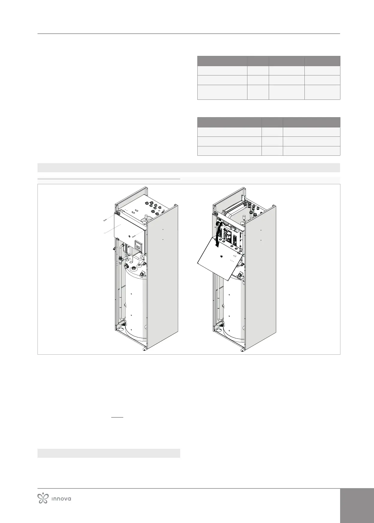
3�15�3 Access to the electrical panel
1� Connection entry
Access to the electrical panel is only permitted to qual-
Before doing any work, make sure that the supply pow-
er is disconnect.
To access:
–
– see chapter "Disassembly and assembly of cosmetic
panels after installation" p.40
To access the connections:
– undo the screws of the closing panel of the electric
panel
– open the panel
3�15�4 Connection
Before connecting the outdoor unit to the electri-
calpowersupply,makesurethatthepowersup-
plytotheoutdoorunithasbeenswitchedo.
It is prohibited to continue if the power supply to the
Use properly sized cables to avoid voltage drops or
overheating.
Before connecting to the terminals, read this manual
carefully.