34
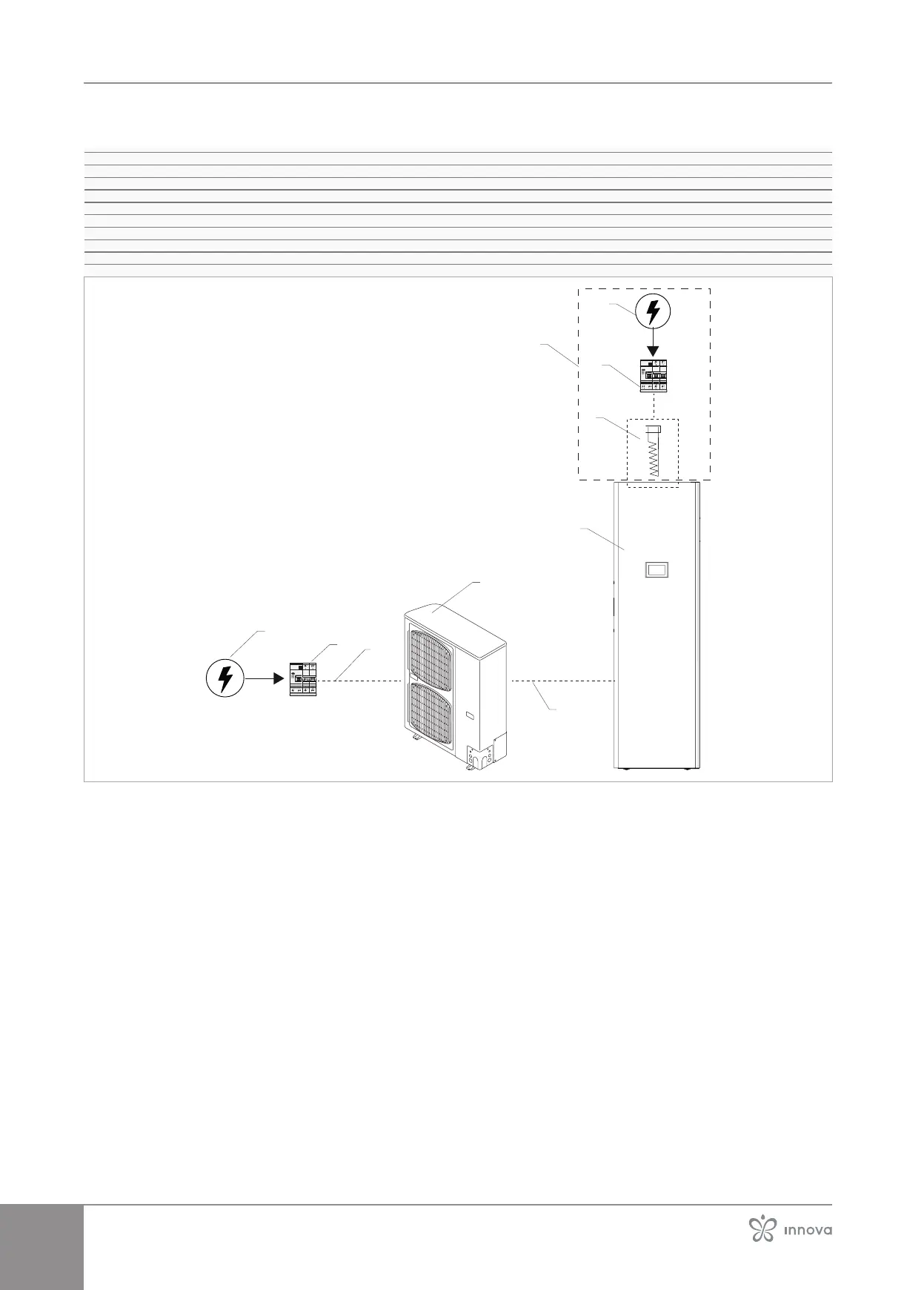
Connection diagram
1� Unit power supply 230/1/50 0 400/3/50 depending on model
2� Protection switch (by installer)
3� Power cable
4�
5� Power line communication outdoor unit - indoor unit
6� Indoor unit
7�
8� Protection switch
9� Emergency heating elements power supply
A Connection of electrical resistance
1
2
3
4
5
6
8
7
A
 Loading...