35
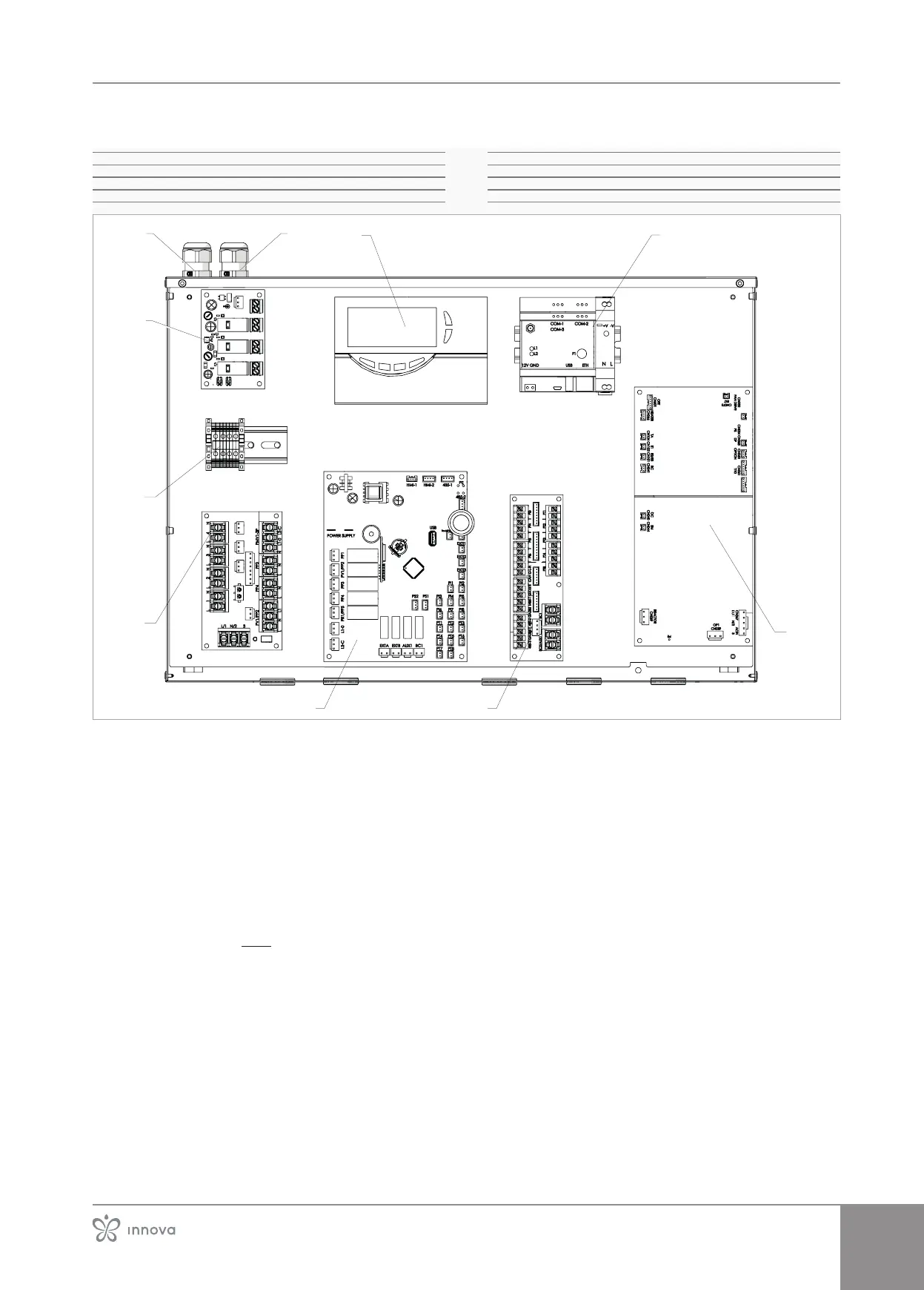
Layout of electrical panel aboard unit
1� Inlet for internal unit power supply
2� Resistance power input
3� Heater kit board (optional kit)
4� Terminal block for earth connection (XP3)
5� Power connection terminal block (XP1)
6� Board INN-PDC-03 (N540162A)
7� Low-voltage terminal block (XP2)
8�
9� Web server kit (opzional kit)
10� Solar unit (solar kit only) (optional kit)
3
5
4
8
To make the connection:
– bring the power cord to the terminal block
– making the connections
– refer to the information in the wiring diagram of the
unit you are installing
The power cable must be sized according to this man-
ual.
Use a double-insulated multi-core cable mod. H07RNF
for outdoor applications in cable duct, or mod, H05VVF
for indoor applications.
For connections, please refer to the diagrams in the
"Connection boards" p.36 section.
 Loading...